 English
 Español
 русский
 عربى
عربىHome / Products / Water Supply and Drainage / Complete Equipment / Sewage Lifting Equipment (Drainage Equipment) / JSS 10O0V /250V Household Sewage Lift
Sewage Lifting Equipment (Drainage Equipment)
JSS 10O0V /250V Household Sewage Lift
Equipment Overview
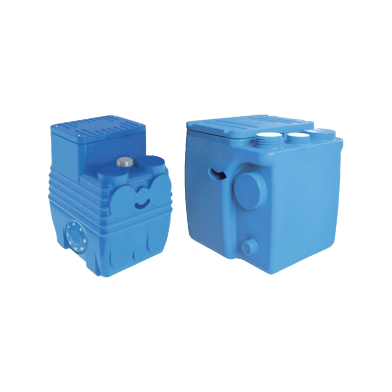
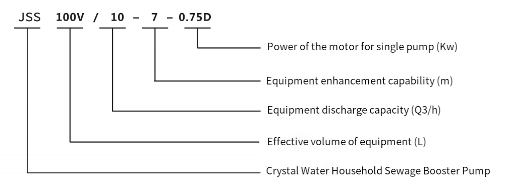
The JSS 100V and JSS250V sewage elevators are integrated underground sewage lifting devices with effective capacities of approximately 100L and 250L, respectively. They are equipped with a single cutting water pump and are suitable for high-end occasions such as villas and small clubs.
JSS100V and JSS250V can collect and lift sewage that cannot flow by gravity to municipal sewage pipes. This product has high integration, small footprint, automatic control, and effectively pretreats sewage and prevents odors. The elevator has reserved multiple water inlets for customers to choose from.
Product Description
Model significance
Equipment Composition
The JSS 100V and JSS250V sewage elevators consist of a PE water collection tank, a cutting type sewage pump, a bent pipe, a UPVC (or stainless steel) outlet pipe, rubber connectors for the inlet pipe, rubber seals, fasteners, and a control box. The entire equipment has a simple structure, few components, and is easy to maintain
Protect. The elevator relies on a liquid level sensor for liquid level control.
1. The outlet pipe of the equipment is made of UPVC pipe with a diameter of 63, and is equipped with a flexible joint with a diameter of 63 for connection with external pipelines.
2. The exhaust holes of the equipment are equipped with UPVC connectors with diameters of 50 and 75, which can be directly connected by inserting the external exhaust pipe.
3. The device has a large effective capacity, which can buffer sewage and reduce the number of device startups. It can be connected to washing machines, bathtubs, showers, toilets, etc.
4. The water collection tank is made of polyethylene composite material by rotational molding, with 5 reserved inlet ports for customers to choose according to site conditions.
5. Built in cutting submersible pump with good cooling effect, operating in S1 sustainable mode, with a maximum of 20 starts per hour. The pump is equipped with a cutting system and can treat impurities such as long fibers in sewage.
Technical and Performance Parameters
1. Technical parameters
|
No. |
Item |
Details |
|
1 |
Medium |
1. General domestic sewage |
|
2 |
Operation Mode |
S1 Continuous Operation (Note: S1 is the code for continuous operation duty of the motor, meaning the motor operates continuously under constant load, sufficient to bring the motor to a thermal steady state) |
|
3 |
Liquid Level Control Method |
Liquid Level Sensor |
|
4 |
Operating Parameters |
1. Maximum allowable liquid temperature: 40℃ 2. Maximum number of starts per hour: 20 times/hour 3. Equipment input power: 0.75/1.1/1.5 (kW) 4. Equipment voltage: Single-phase 220 (V) |
|
5 |
Electrical Parameters |
Equipment starting current/running current: 0.75 kW single-phase 25/5.6 (A) 1.1 kW single-phase 32/7.5 (A) 1.5 kW single-phase 42/10 (A) Equipment operating frequency: 50 (Hz) Protection class: IP68 (Note: IP68 is the enclosure protection class for electrical equipment; 6 indicates complete protection against solid intrusion, and 8 indicates that the equipment can work normally when immersed in water for a long time under specified pressure) |
|
6 |
Motor Performance |
Insulation class: Class F (Note: Class F insulation means the maximum allowable operating temperature of the motor winding insulation material is 155℃) |
|
7 |
Connection Method |
Outlet connection: φ63 UPVC union (Note: "Union" refers to a fitting used in pipeline connections for easy disassembly; φ63 means the outer diameter of the pipeline is 63 mm) Vent pipe connection: φ50 UPVC pipe fitting (φ50 means the outer diameter of the pipeline is 50 mm) Inlet connection: φ110 rubber bellows joint (φ110 means the outer diameter of the pipeline is 110 mm |
2. Performance parameters
| Serial number | Model | Emission capacity | Enhance capabilities | Motor power | Power supply voltage | Size of water collection tank | Inlet and outlet pipe diameter (mm) | Suggested minimum installation space (mm) | ||||||
| A | B | H | Inlet pipe diameter | Outlet pipe diameter | Exhaust pipe diameter | |||||||||
| m³/h | m | Kw | V | mm | mm | mm | D1 | D2 | D3 | L | W | H | ||
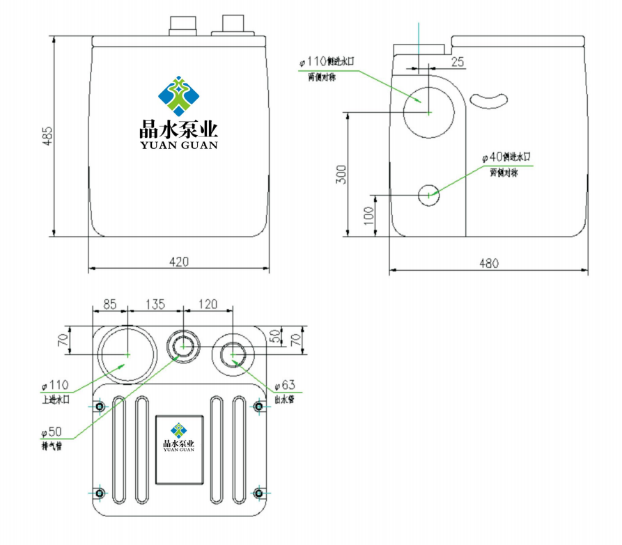
| 1 | JSS 100V/7-7-0.55D | 7 | 7 | 0.55 | 220 | 420 | 480 | 465 | 110 | 63 | 50 | 450 | 500 | 500 |
| 2 | JSS 100V/7-10-0.75D | 7 | 10 | 0.75 | 220 | 420 | 480 | 465 | 110 | 63 | 50 | 450 | 500 | 500 |
| 3 | JSS 100V/10-7-0.75D | 10 | 7 | 0.75 | 220 | 420 | 480 | 465 | 110 | 63 | 50 | 450 | 500 | 500 |
| 4 | JSS 100V/10-10-0.75D | 10 | 10 | 0.75 | 220 | 420 | 480 | 465 | 110 | 63 | 50 | 450 | 500 | 500 |
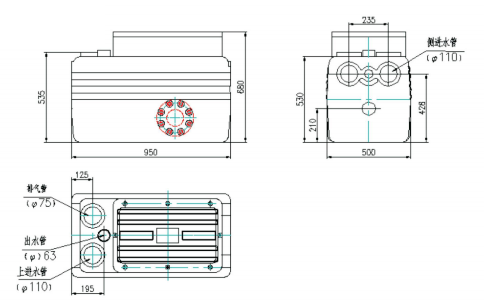
| 5 | JSS 250V/7-12-1.1D | 7 | 12 | 11 | 220 | 500 | 950 | 680 | 110 | 63 | 63 | 550 | 1000 | 700 |
| 6 | JSS 250V/7-15-1.5D | 7 | 15 | 15 | 220 | 500 | 950 | 680 | 110 | 63 | 63 | 550 | 1000 | 700 |
| 7 | JSS 250V/10-12-1.1D | 10 | 12 | 11 | 220 | 500 | 950 | 680 | 110 | 63 | 63 | 550 | 1000 | 700 |
| 8 | JSS 250V/10-15-1.5D | 10 | 15 | 15 | 220 | 500 | 950 | 680 | 110 | 63 | 63 | 550 | 1000 | 700 |
| 9 | JSS 250V/15—7-1.5D | 15 | 7 | 15 | 220 | 500 | 950 | 680 | 110 | 63 | 63 | 550 | 1000 | 700 |
| 10 | JSS250V/15-10-1.5D | 15 | 10 | 15 | 220 | 500 | 950 | 680 | 110 | 63 | 63 | 550 | 1000 | 700 |
| 11 | JSS 250V/10-10-0.75 | 10 | 10 | 0.75 | 380 | 500 | 950 | 680 | 110 | 63 | 63 | 550 | 1000 | 700 |
| 12 | JSS250V/10-15-1.5 | 10 | 15 | 15 | 380 | 500 | 950 | 680 | 110 | 63 | 63 | 550 | 1000 | 700 |
| 13 | JSS 250V/10-20-2.2 | 10 | 20 | 22 | 380 | 500 | 950 | 680 | 110 | 63 | 63 | 550 | 1000 | 700 |
| 14 | JSS250V/10-25-3 | 10 | 25 | 3 | 380 | 500 | 950 | 680 | 110 | 63 | 63 | 550 | 1000 | 700 |
| 15 | JSS250V/10-30-3 | 10 | 30 | 3 | 380 | 500 | 950 | 680 | 110 | 63 | 63 | 550 | 1000 | 700 |
| 16 | JSS250V/15-10-1.1 | 15 | 10 | 11 | 380 | 500 | 950 | 680 | 110 | 63 | 63 | 550 | 1000 | 700 |
| 17 | JSS 250V/15-15-1.5 | 15 | 15 | 15 | 380 | 500 | 950 | 680 | 110 | 63 | 63 | 550 | 1000 | 700 |
| 18 | JSS 250V/15-20-2.2 | 15 | 20 | 22 | 380 | 500 | 950 | 680 | 110 | 63 | 63 | 550 | 1000 | 700 |
19 |
JSS 250V/15-25-3 | 15 | 25 | 3 | 380 | 500 | 950 | 680 | 110 | 63 | 63 | 550 | 1000 | 700 |
| 20 | JSS 250V/15-30-3 | 15 | 30 | 3 | 380 | 500 | 950 | 680 | 110 | 63 | 63 | 550 | 1000 | 700 |
Dimensions, Installation Method, and Schematic Diagram
1. External dimensions:
100V box external dimensions
Dimensions of 250V box body
2. Installation method:
1. According to the location of the inlet pipe on site, select the corresponding inlet and use a φ 110 hole opener (provided) to open the hole. Place one end of the rubber corrugated pipe connecting pipe placed in the box on the inlet pipe and lock it with a clamp. Then, place the other end on the corresponding inlet of the equipment and lock it with a clamp;
2. Apply adhesive to the UPVC with a diameter of 63 and insert it into the water outlet pipe. Connect the water outlet pipe according to the site conditions;
3. Connect the exhaust port with a UPVC pipe of diameter 50 according to the on-site situation;
4. Connect the water pump cable and float control line to the control box as required.
3. Installation diagram:
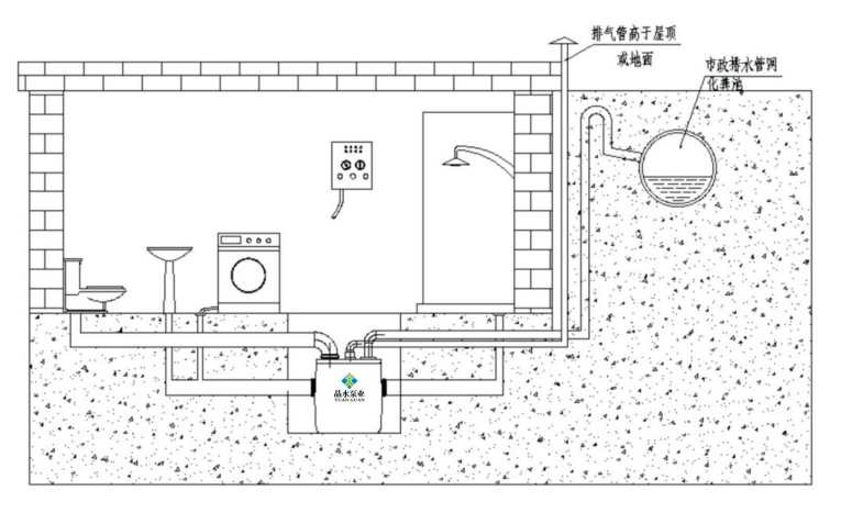
Installation precautions
1. The sewage elevator needs to be fixed on a flat surface;
2. Leave sufficient space around the sewage elevator to facilitate the installation of isolation valves (to be provided by the user) at the inlet of the water collection tank for easy maintenance;
3. The inlet pipe, outlet pipe, and ventilation pipe on the water collection tank must not have any pressure. If the pipeline is long, please provide support;
4. When laying the sewage pipes of various sanitary ware, a certain slope should be considered to ensure that the sewage can flow into the lifting device by gravity,
All horizontal pipes must have a downward slope: drainage pipes: minimum 1%. Inlet pipe: minimum 3%.
5. When connecting the outlet pipe to the shared drainage pipe, a gooseneck pipe or a reverse water seal must be installed to prevent sewage from flowing back;
6. If the sewage elevator is installed in a basement with groundwater leakage, please install a separate drainage pump;
7. When disassembling, the motor power must be cut off;
8. It is strictly prohibited to lift water pumps and float cables.
9. The inlet pipe must be correctly connected to the elevator. Please check the tightness of the connection before starting the elevator.
Start
1. Check if the installation is correct.
2. Connect the power supply.
3. Fill the water collection tank with water and check if the water pump starts normally when it reaches the pump start height. If the water level drops to the pump stop level, check if the water pump stops working.
4. Check if all pipeline connections are tight.
Fault diagnosis
|
Malfunction |
Cause |
Maintenance Method |
|
The motor does not operate after the water tank is filled to the start liquid level. |
a) Power supply is not connected. b) Liquid level sensor is not connected. c) Liquid level sensor is faulty. |
a) Check the power connection status. b) Replace the liquid level sensor. |
|
The motor makes noise but does not operate normally. |
a) Impeller is faulty. b) Motor is faulty. |
a) Turn off the power and check if the impeller rotates freely and normally. b) Replace the water pump. |
|
The motor operates unsteadily continuously or intermittently in a regular pattern. |
a) Water inlet of the facility leaks. b) Drain pipe has water backflow. c) Liquid level sensor is faulty. |
a) Check the leaking water pipe/water tank. b) Check the internal check valve. c) Replace the liquid level sensor. |
|
The motor works normally but does not drain water. |
a) The lifter is blocked. b) There is air in the lifter. c) The inside of the drain pipe is blocked. |
a) Remove the obstruction. b) Check if the water tank vent pipe is unobstructed. c) Remove the obstruction. |
|
Slow drainage. |
a) Air vent is blocked. b) Check valve is blocked. c) The drain pipe is too long or excessively bent. |
a) Check if the internal air inlet is blocked. b) Check the working condition of the leaking valve. c) Modify the piping project to reduce pipe bends or increase the bend radius. Replace with a high-lift water pump. |
Related products


Copyright © JINGSHUI PUMP (SHANGHAI) CO., LTD. All Rights Reserved.
Wholesale JSS 10O0V /250V Household Sewage Lift Manufacturers
China JSS 10O0V /250V Household Sewage Lift Factory
