 English
 Español
 русский
 عربى
عربىHome / Products / Water Pump / Centrifugal Pumps / Axial Flow Pumps / QH Series Submersible Mixed Flow Pump
Axial Flow Pumps
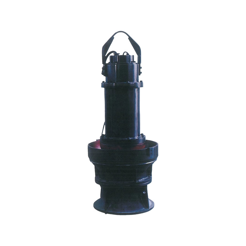
QH Series Submersible Mixed Flow Pump
Product Introduction
Submersible pump stations have rapidly developed due to their simple construction, low engineering cost, convenient maintenance and management, easy operation and automation, good work reliability, and environmental beautification.
The main equipment of a submersible pump station is the submersible electric pump (referred to as submersible pump), which includes the QZB submersible axial flow pump and QH (B) submersible mixed flow pump. It is an electromechanical product that combines the motor with the axial flow pump and mixed flow pump, and is an updated version of the traditional long axis axial flow pump and mixed flow pump.
Product Description
Submersible pumps and traditional long shaft pumps have significant advantages in terms of usage scenarios, inlet and outlet conditions, and characteristic parameters, as well as the following:
Save over 30% of the total investment in pump station engineering:
★ Save over 40% in construction period:
★ Unit installation time saved by over 95%;
Reduce the weight of the unit by more than 50%:
★ Save investment in flood control walls for pump stations:
★ Low maintenance costs:
★ No operating noise, easy to operate, and easy to automate:
The low height of ground buildings can eliminate the need for pump room construction, and even allow for the construction of pump stations below ground level.
Therefore, new and old customers of axial flow pumps and mixed flow pumps can easily replace submersible pumps in new pump station projects, and can be updated with submersible pumps in old pump station renovation projects. This type of pump is mainly suitable for the following situations:
★ Irrigation and Drainage of Farmland:
★ Municipal discharge of rainwater and mild sewage:
★ Process water and cooling water in industry:
★ Water conservancy middle note project.
Our company's submersible pumps come in ten nominal outlet diameters, including 350, 500, 600, 700, 800, 900, 1000, 1200, 1400, and 1600. The flow range is 0.12-12m3/s, the head range is 2-14m, the power range is 7.5-630kW, and the voltage levels are 380V, 660V, 3kV, 6kV, and 10kV.
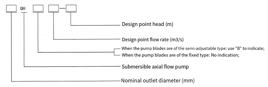
Model Description
1. Submersible axial flow pump
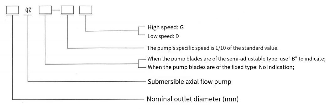
2. Submersible mixed flow pump
Structural Description
The QZB submersible axial flow pump and QH (B) submersible mixed flow pump are composed of four major parts: the inlet horn mouth, impeller components, impeller housing, and guide vane body. The submersible motor is a fully sealed dry-type asynchronous motor. The motor is enclosed by a casing, and there is a static sealing device at the cable outlet on the upper end of the motor. There is a rotating sealing device at the shaft cover on the lower end of the motor. The submersible motor has all the safety and reliability performance for submersible operation. There are monitoring, alarm and protection devices for sealing leakage, coil and bearing temperature rise, which do not affect the early leakage of the motor's normal operation (only alarm). When the coil temperature exceeds 135 ℃ and the bearing temperature exceeds 90C, power-off protection is used, and all protectors are monitored by a dedicated submersible pump protector to ensure the safe use of the submersible pump.
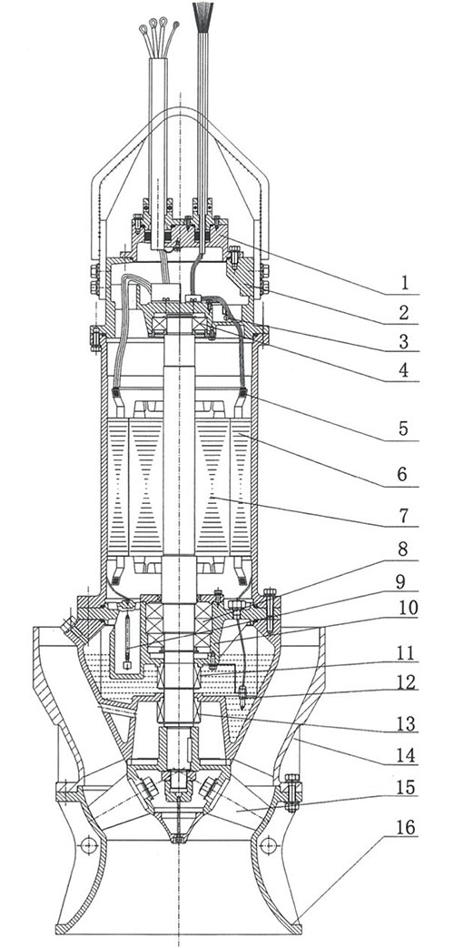
General drawing of QHB submersible mixed flow pump structure
1. Terminal box cover
2. Upper cover
3. Leakage alarm
4. Upper bearing
5. Thermal protector
6. Stator
7. Rotor
8. Lower bearing
9. Leakage alarm
10. Lower end cover
11. Upper mechanical seal
12. Electrode probe
13. Lower mechanical seal
14. Guide vane body
15. Impeller components
16. Water inlet horn
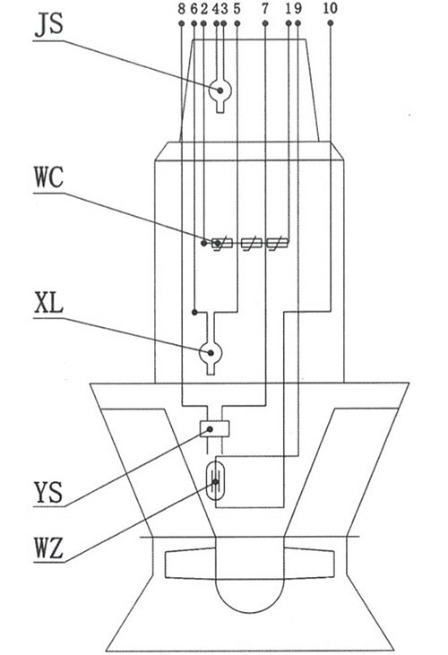
Layout of internal sensors for submersible axial flow pumps and mixed flow pumps
The sensor output signal is received by the submersible pump protector. The protector outputs a switch signal for each output signal, including switch or analog signals, and displays an alarm flashing signal on the protector.
| JS | Immersion sensor | Upper wiring chamber | switch signal | Normally Open | ≥18.5kW |
| WC | Winding temperature sensor | Inside the motor winding | Thermal switch signal | Normally closed | |
| PT100 platinum resistance signal | Resistance signal | According to user requirements | |||
| XL | Leak sensor | Inside the motor chamber | Switch signal | Normally Open | |
| YS | Temperature sensor | Oil chamber | Analog signal | >30k Ω | ≥18.5kW |
| WZ | Lower axle temperature sensor | Lower bearing chamber | Thermal switch signal | Normally closed | ≥132kW |
| PT100 platinum resistance signal | Resistance signal | According to user requirements |
Performance parameters and spectra
Performance parameters and spectrum of mixed flow pump QH (B)
1. Performance parameters of blade integral submersible mixed flow pump (QH type)
| Model | Traffic Q | Head H (m) | Speed n (r/min) | Power P (kW) | Efficiency η (%) | ||
| (m³/h) | (L/s) | Shaft power | Motor power | ||||
| 350QHO.1-5 | 279 360 408 |
77.5 100 113.3 |
6.35 5 3.65 |
1460 | 6.5 6.2 5.5 |
11 | 74.7 79.3 74.2 |
| 350QH0.2-11 | 469 720 837 |
130.3 200 232.5 |
13.75 11 8.85 |
980 | 24.6 27.5 28.0 |
37 | 71.5 78.5 72 |
| 350QH0.3-28 | 787 1080 1311 |
218.6 300 364.2 |
30.45 28 22.85 |
740 | 83.7 99.9 109.0 |
110 | 77.9 82.4 74.8 |
| 350QH0.3-40 | 861 1080 1498 |
239.2 300 416.1 |
44.05 40 32.05 |
980 | 132.5 142.7 170.2 |
185 | 77.9 82.4 76.8 |
| 400QH0.3-10 | 714.2 1080 1297.7 |
198.4 300 360.5 |
14.75 10 6.45 |
980 | 37.2 35.5 29.6 |
45 | 77.1 82.7 77.1 |
| 500QH0.5-32 | 1264 1800 2396 |
351.1 500 665.6 |
36.45 32 25.05 |
740 | 171.3 197.5 219.6 |
250 | 73.2 79.4 74.4 |
| 500QH0.6-35 | 1443 2160 2752 |
400.8 600 764.4 |
39.05 35 28.05 |
590 | 208.7 260.8 275.4 |
310 | 73.5 78.9 76.3 |
| 700QH0.9-13 | 2331 3240 3870 |
647.5 900 1075.0 |
16.75 13 9.85 |
740 | 138.2 141.5 135.6 |
185 | 76.9 81 76.5 |
| 700QH1.1-20 | 2738 3960 4798 |
760.6 1100 1332.8 |
25.55 20.05 15.65 |
740 | 251.9 266.5 265.5 |
315 | 75.6 80.9 77 |
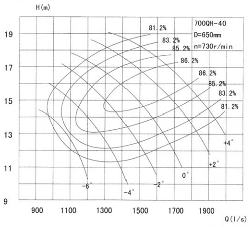
2. Performance parameters and performance curves of blade semi adjustable submersible mixed flow pump (QHB type)
500QH-50 Performance Table
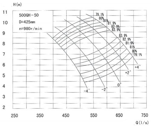
| Blade placement angle | Traffic Q | Head H (m) | Speed n (r/min) | Power P (kW) | Efficiency η (%) | Impeller diameter (mm) | ||
| (m³/h) | (L/s) | Shaft power | Motor power | |||||
| -4° | 1495 1621 1801 |
415.3 450.3 500.3 |
8.05 6.85 5.25 |
980 | 40.6 36.1 31.9 |
55 | 80.7 83.8 80.7 |
425 |
| -2° | 1621 1801 1959 |
450.3 500.3 544.2 |
8.55 7.35 6.05 |
46.1 43.0 39.4 |
81.8 83.8 81.8 |
|||
| 0° | 1729 1981 2197 |
480.3 550.3 610.3 |
9.55 8.05 6.05 |
56.3 51.8 44.8 |
75 | 79.9 83.8 80.7 |
||
| +2° | 1959 2161 2319 |
544.2 600.3 644.2 |
9.55 8.25 6.85 |
62.3 57.9 53.6 |
81.8 83.8 80.7 |
|||
| +4° | 2053 2269 2467 |
570.3 630.3 685.3 |
10.05 8.75 7.05 |
70.1 64.5 59.3 |
80.1 83.8 79.9 |
|||
600QH-50 Performance Table
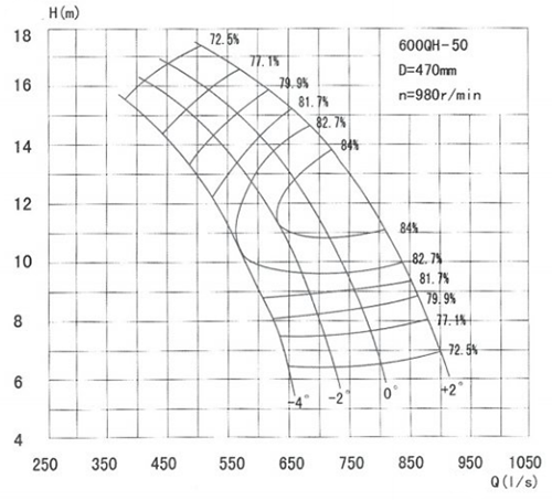
| Blade placement angle | Traffic Q | Head H (m) | Speed n (r/min) | Power P (kW) | Efficiency η (%) | Impeller diameter (mm) | ||
| (m³/h) | (L/s) | Shaft power | Motor power | |||||
| -4° | 1621 2089 2305 |
450.3 580.3 640.3 |
14.35 10.25 7.47 |
980 | 82.13 70.57 60.79 |
90 | 77.1 82.6 77.1 |
470 |
| -2° | 1711 2323 2575 |
475.3 645.3 715.3 |
15.25 11.05 7.55 |
92.13 84.09 68.64 |
110 | 77.1 83.1 77.1 |
||
| 0° | 1847.8 2459.8 2845 |
513.3 683.3 790.3 |
15.95 12.05 7.70 |
104.06 96.06 77.35 |
132 | 77.1 84 77.1 |
||
| +2° | 2053 2809 3187 |
570.3 780.3 885.3 |
16.85 12.05 7.95 |
122.14 109.69 89.46 |
77.1 84 77.1 |
|||
700QH-50 Performance Table
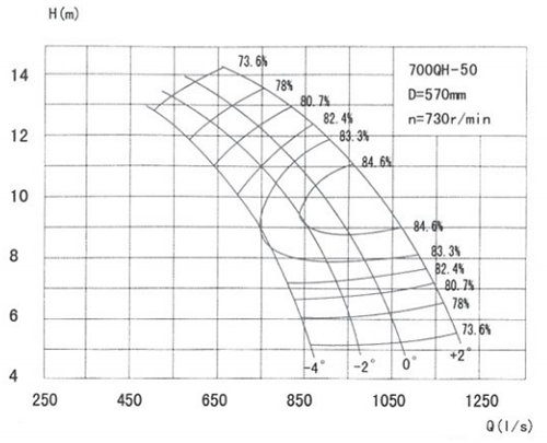
| Blade placement angle | Traffic Q | Head H (m) | Speed n (r/min) | Power P (kW) | Efficiency η (%) | Impeller diameter (mm) | ||
| (m³/h) | (L/s) | Shaft power | Motor power | |||||
| -4° | 2341 2845 3025 |
650.3 790.3 840.3 |
11.05 8.05 6.65 |
730 | 87.91 75.02 67.94 |
110 | 80.1 83.1 80.6 |
570 |
| -2° | 2736 3115 3396 |
760.0 865.3 943.3 |
10.85 9.05 6.55 |
98.07 90.71 75.60 |
82.4 84.6 80.1 |
|||
| 0° | 2701 3241 3701 |
750.3 900.3 1028.1 |
12.35 10.05 7.05 |
112.66 104.81 87.58 |
132 | 80.6 84.6 81.1 |
||
| +2° | 2971 3493 4123 |
825.3 970.3 1145.3 |
13.05 11.05 7.65 |
131.44 124.20 104.58 |
160 | 80.3 84.6 82.1 |
||
(Five leaf blade)
700QH-40 Performance Table
| Blade placement angle | Traffic Q | Head H (m) | Speed n (r/min) | Power P (kW) | Efficiency η (%) | Impeller diameter (mm) | ||
| (m³/h) | (L/s) | Shaft power | Motor power | |||||
| -6° | 3421 3648 4047 |
950.3 1013.3 1124.2 |
13.95 12.75 10.45 |
730 | 159.01 153.85 140.91 |
185 | 81.7 82.3 81.7 |
650 |
| -4° | 3590 4220 4731 |
997.2 1172.2 1314.2 |
16.45 13.75 10.25 |
196.77 183.46 161.58 |
220 | 81.7 86.1 81.7 |
||
| -2° | 3821 4674 5325 |
1061.4 1298.3 1479.2 |
17.95 14.75 10.75 |
228.53 217.97 190.73 |
250 | 81.7 86.1 81.7 |
||
| 0° | 4105 5073 5815 |
1140.3 1409.2 1615.3 |
18.85 15.75 11.55 |
257.83 252.62 223.79 |
280 | 81.7 86.1 81.7 |
||
| +2° | 4562 5531 6326 |
1267.2 1536.4 1757.2 |
19.85 16.65 12.45 |
301.73 291.16 262.42 |
355 | 81.7 86.1 81.7 |
||
| +4° | 4904 5930 6783 |
1362.2 1647.2 1884.2 |
20.45 17.65 13.55 |
334.15 330.92 306.24 |
400 | 81.7 86.1 81.7 |
||
900QH-40 Performance Table
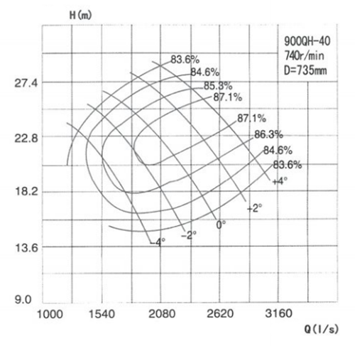
| Blade placement angle | Traffic Q | Head H (m) | Speed n (r/min) | Power P (kW) | Efficiency η (%) | Impeller diameter (mm) | ||
| (m³/h) | (L/s) | Shaft power | Motor power | |||||
| -4° | 5652 6296 7387 |
1570 1749 2052 |
23.5 21.6 16.3 |
740 | 453.5 450.6 399.3 |
500 | 83.07 85.46 85.17 |
735 |
| -2° | 6678 7232 8348 |
1855 2009 2319 |
23.9 22.0 16.7 |
531.7 517.6 465.0 |
560 | 85.14 87.04 85.15 |
||
| 0° | 7509 8096 9277 |
2086 2249 2577 |
24.3 22.4 17.3 |
597.5 589.3 535.3 |
710 | 86.53 87.2 84.79 |
||
| +2° | 8571 9115 10274 |
2591 2532 2854 |
24.9 23.0 17.9 |
692.6 680.4 619.9 |
87.17 87.2 84.0 |
|||
| +4° | 9464 10011 11185 |
2629 2781 3107 |
25.4 23.5 18.5 |
780.4 765.0 703.1 |
800 | 87.2 87.2 83.44 |
||
900QH-50 Performance Table
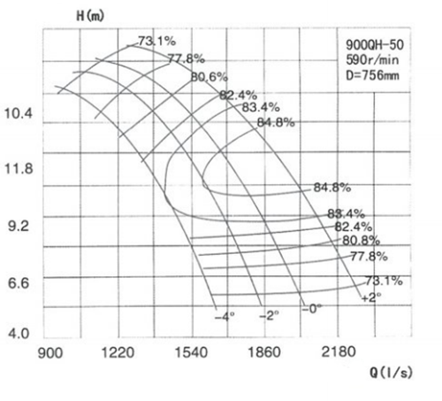
| Blade placement angle | Traffic Q | Head H (m) | Speed n (r/min) | Power P (kW) | Efficiency η (%) | Impeller diameter (mm) | ||
| (m³/h) | (L/s) | Shaft power | Motor power | |||||
| -4° | 4597 5083 5731 |
1277 1412 1592 |
12.3 10.2 6.59 |
590 | 196.1 176.9 140.1 |
260 | 81.41 83.39 76.43 |
756 |
| -2° | 5296 5767 6408 |
1471 1602 1780 |
12.5 10.5 6.88 |
226.6 202.8 161.9 |
82.88 84.62 77.17 |
|||
| 0° | 5782 6289 6995 |
1606 1747 1943 |
12.7 10.7 7.17 |
248.2 225.4 181.3 |
83.91 84.8 78.18 |
|||
| +2° | 6469 7024 7805 |
1797 1951 2168 |
13.0 11.1 7.6 |
282.8 260.1 208.9 |
315 | 84.39 84.8 78.96 |
||
1000QH-40 Performance Table
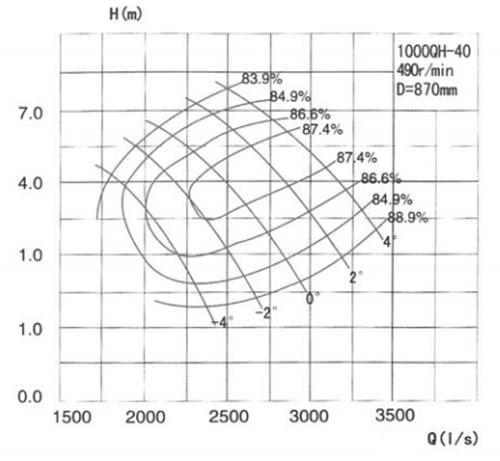
| Blade placement angle | Traffic Q | Head H (m) | Speed n (r/min) | Power P (kW) | Efficiency η (%) | Impeller diameter (mm) | ||
| (m³/h) | (L/s) | Shaft power | Motor power | |||||
| -4° | 5310 6995 7912 |
1475 1943 2206 |
15.4 13.39 10.89 |
490 | 271.6 297.7 272.6 |
315 | 82.06 85.72 86.50 |
870 |
| -2° | 6880 8021 8989 |
1911 2228 2497 |
15.67 13.61 11.15 |
351.8 340.9 315.8 |
400 | 83.52 87.27 86.46 |
||
| 0° | 7808 9011 10030 |
2169 2503 2786 |
15.86 13.85 11.43 |
397.6 389.2 363.0 |
450 | 84.92 87.40 86.01 |
||
| +2° | 9072 10152 11146 |
2520 2820 3096 |
16.17 14.16 11.76 |
462.2 448.3 420.4 |
500 | 86.45 87.40 84.95 |
||
| +4° | 10069 11149 12161 |
2797 3097 3378 |
16.44 14.46 12.1 |
519.9 502.6 477.8 |
560 | 86.73 87.40 83.90 |
||
1000QH-50 Performance Table
| Blade placement angle | Traffic Q | Head H (m) | Speed n (r/min) | Power P (kW) | Efficiency η (%) | Impeller diameter (mm) | ||
| (m³/h) | (L/s) | Shaft power | Motor power | |||||
| -4° | 5486 6354 7096 |
1524 1765 1971 |
11.99 9.56 6.81 |
490 | 225.0 200.0 162.7 |
250 | 79.63 83.57 80.97 |
870 |
| -2° | 6430 6800 7960 |
1786 1889 2211 |
12.17 9.85 7.02 |
260.9 228.4 188.6 |
280 | 81.72 85.09 80.80 |
||
| 0° | 6419 7920 8708 |
1783 2200 2419 |
13.47 10.01 7.23 |
296.1 254.0 210.6 |
355 | 79.54 85.10 81.42 |
||
| +2° | 7257 8856 9734 |
2016 2460 2704 |
13.60 10.27 7.53 |
332.4 291.1 244.9 |
400 | 81.23 85.10 81.57 |
||
1200QH-40 Performance Table
| Blade placement angle | Traffic Q | Head H (m) | Speed n (r/min) | Power P (kW) | Efficiency η (%) | Impeller diameter (mm) | ||
| (m³/h) | (L/s) | Shaft power | Motor power | |||||
| -4° | 9061 10256 11290 |
2517 2849 3136 |
17.16 14.84 12.02 |
490 | 501.3 475.4 434.4 |
560 | 84.53 87.24 85.14 |
970 |
| -2° | 9918 11473 12780 |
2755 3187 3550 |
18.39 15.55 12.31 |
585.4 555.7 504.0 |
630 | 84.89 87.50 85.05 |
||
| 0° | 10476 12208 14245 |
2910 3391 3957 |
19.54 17.09 12.62 |
660.3 649.7 579.4 |
710 | 84.46 87.50 84.56 |
||
| +2° | 12125 13691 15278 |
3368 3803 4244 |
20.06 17.63 14.27 |
773.1 751.6 698.9 |
800 | 85.73 87.50 85.00 |
||
| +4° | 13399 14969 16592 |
3722 4158 4609 |
20.52 18.14 14.83 |
872.6 845.5 799.0 |
900 | 85.85 87.50 84.09 |
||
1200QH-50 Performance Table
| Blade placement angle | Traffic Q | Head H (m) | Speed n (r/min) | Power P (kW) | Efficiency η (%) | Impeller diameter (mm) | ||
| (m³/h) | (L/s) | Shaft power | Motor power | |||||
| -4° | 7380 8863 9738 |
5050 2462 2705 |
15.00 11.71 8.85 |
490 | 383.8 337.6 284.5 |
450 | 78.61 83.77 82.59 |
870 |
| -2° | 8730 10105 10951 |
2425 2807 3042 |
15.20 11.92 9.08 |
445.5 384.9 327.8 |
500 | 81.14 85.30 82.67 |
||
| 0° | 9270 11059 11984 |
2575 3072 3329 |
15.88 12.10 9.30 |
495.2 427.6 365.9 |
560 | 81.03 85.30 82.97 |
||
| +2° | 10465 12380 13414 |
2907 3439 3726 |
16.10 12.38 9.62 |
556.4 489.8 423.1 |
630 | 82.50 85.30 83.13 |
||
1400QH-40 Performance Table
| Blade placement angle | Traffic Q | Head H (m) | Speed n (r/min) | Power P (kW) | Efficiency η (%) | Impeller diameter (mm) | ||
| (m³/h) | (L/s) | Shaft power | Motor power | |||||
| -4° | 15156 17374 19228 |
4210 4826 5314 |
17.18 14.90 12.10 |
370 | 839.7 805.1 737.7 |
900 | 84.51 87.62 86.95 |
1277 |
| -2° | 17730 19786 21744 |
4925 5496 6040 |
17.44 15.17 12.41 |
971.1 929.2 855.5 |
1100 | 86.73 88.00 85.94 |
||
| 0° | 18288 20941 23796 |
5080 5817 6610 |
19.00 16.81 13.36 |
1108.7 1189.9 1004.6 |
1200 | 85.40 88.00 86.24 |
||
| +2° | 21287 23652 26330 |
5913 6570 7314 |
19.35 17.17 13.89 |
1290.7 1257.4 1167.4 |
1400 | 86.96 88.00 85.36 |
||
| +4° | 23641 25996 28634 |
6567 7221 7954 |
19.68 17.51 14.42 |
1451.7 1409.9 1331.6 |
1500 | 87.27 88.00 84.49 |
||
1400QH-50 Performance Table
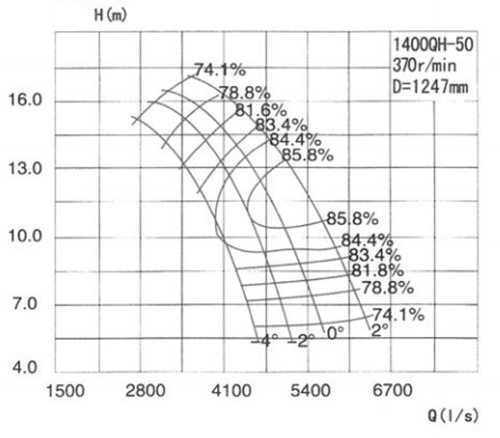
| Blade placement angle | Traffic Q | Head H (m) | Speed n (r/min) | Power P (kW) | Efficiency η (%) | Impeller diameter (mm) | ||
| (m³/h) | (L/s) | Shaft power | Motor power | |||||
| -4° | 10825 14051 15505 |
3007 3903 4307 |
14.71 10.81 7.90 |
370 | 564.5 490.8 406.9 |
630 | 76.87 84.35 82.06 |
1277 |
| -2° | 12604 15840 17406 |
3501 4400 4835 |
15.27 11.30 8.14 |
666.7 569.2 470.8 |
710 | 78.65 85.77 81.97 |
||
| 0° | 13990 17320 19040 |
3886 4811 5289 |
15.40 11.50 8.36 |
734.0 632.3 525.6 |
800 | 80.00 85.80 82.53 |
||
| +2° | 15851 19372 21290 |
4403 5381 5914 |
15.61 11.78 8.70 |
824.6 724.7 610.9 |
900 | 81.78 85.80 82.64 |
||
Installation form and size
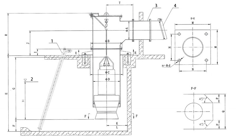
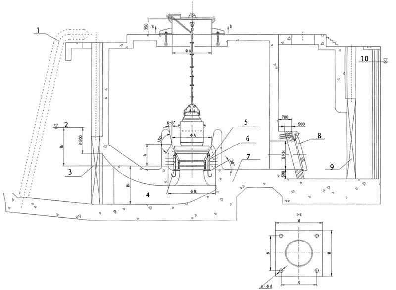
The smaller QZB series submersible axial flow pump and QHB series submersible mixed flow pump adopt open inlet, and the installation forms include wellbore bend installation, steel wellbore installation, and concrete prefabricated wellbore installation. The installation of bent pipes and steel shafts is provided by our company as a complete set of shafts. The installation of precast concrete shafts is provided by our company with installation bases (including anti rotation devices) and covers. During installation, lift the submersible pump into the wellbore until it reaches the bottom. The inclined surface on the guide vane body matches the inclined surface of the support, and the water stop rubber (O-ring) plays a sealing role. Larger submersible pumps (with impeller diameters generally above 1 meter) are installed in a form with a closed inlet channel.
1. Installation and size of wellbore bend pipe
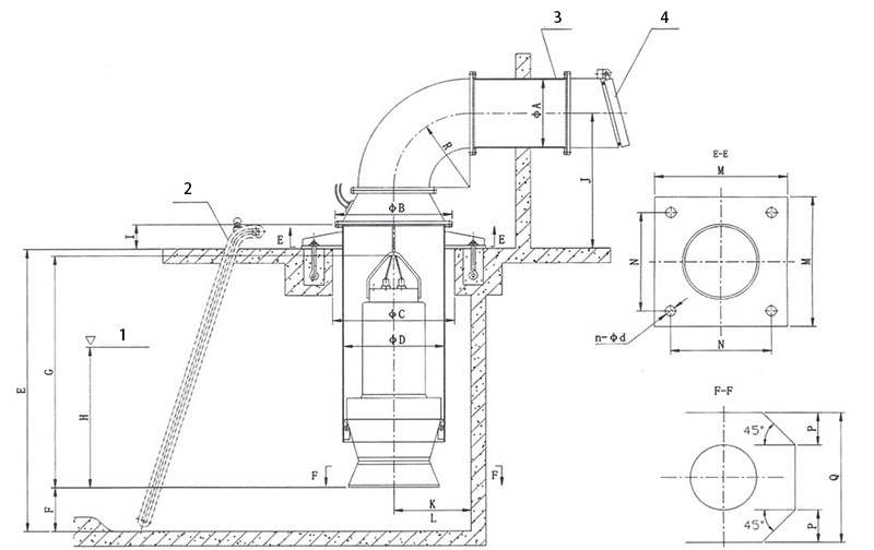
1. Minimum water level
2. Trash rack
3. Wall penetrating pipe
4. Tap the door
Note:
(1) The dimensions in the table refer to the installation dimensions of the pump and the hydraulic control dimensions designed for the pump station. The hydraulic dimensions designed for the pump station are only for reference.
(2) Dimension A is determined based on the flow rate to control the flow rate and reduce hydraulic losses. The dimensions in the table are reference values and can be appropriately increased if necessary. Dimensions E and J are determined based on the specific conditions of the pump station. Dimension R is the minimum reference size and can be appropriately increased if conditions permit. The above dimensions are determined according to user requirements.
(3) The distance between the pump center and the rear pool wall is ≤ K.
(4) The center distance between two pumps in the same pool is ≥ L.
Installation Dimension Table for Shaft Bend (QHB)
| Serial number | Model | ΦA | ΦB | ΦC | ΦD | R | M | N | n-φd | F | H | G | I | K | L | Q | P | Axial water thrust(N) |
| 1 | 350QH0.1-5 | 400 | 755 | 800 | 600 | 500 | 1320 | 1150 | 4-28 | 205 | 555 | 1735 | 210 | 490 | 1450 | 1000 | 240 | 1050 |
| 2 | 350QH0.2-11 | 400 | 975 | 1050 | 800 | 700 | 1580 | 1350 | 4-36 | 295 | 705 | 2018 | 210 | 590 | 1550 | 1550 | 390 | 4950 |
| 3 | 350QH0.3-28 | 400 | 1175 | 1225 | 1000 | 800 | 1820 | 1600 | 4-40 | 395 | 815 | 2580 | 230 | 690 | 1750 | 1750 | 440 | 19550 |
| 4 | 350QH0.3-40 | 400 | 1175 | 1225 | 1000 | 800 | 1820 | 1600 | 4-40 | 395 | 805 | 3180 | 230 | 690 | 1750 | 1750 | 440 | 24650 |
| 5 | 400QH0.3-10 | 400 | 975 | 1050 | 800 | 700 | 1580 | 1350 | 4-36 | 295 | 705 | 2018 | 210 | 590 | 1550 | 1550 | 390 | 6250 |
| 6 | 500QH0.5-32 | 600 | 1405 | 1450 | 1200 | 1200 | 2120 | 1900 | 4-40 | 395 | 855 | 3210 | 270 | 990 | 2350 | 2350 | 590 | 33250 |
| 7 | 500QH-50 | 600 | 975 | 1050 | 800 | 700 | 1580 | 1350 | 4-36 | 395 | 1105 | 2270 | 210 | 590 | 1550 | 1550 | 390 | 17550 |
| 8 | 500QH0.6-35 | 600 | 1520 | 1600 | 1300 | 1200 | 2250 | 2000 | 4-40 | 495 | 755 | 2815 | 310 | 990 | 2750 | 2750 | 690 | 45350 |
| 9 | 600QH-50 | 700 | 1175 | 1225 | 1000 | 900 | 1820 | 1600 | 4-40 | 445 | 1005 | 2310 | 230 | 690 | 1750 | 1750 | 440 | 29550 |
| 10 | 700QHB0.9-13 | 800 | 1305 | 1365 | 1100 | 900 | 1980 | 1700 | 4-40 | 645 | 1205 | 3030 | 230 | 790 | 1950 | 1950 | 490 | 19750 |
| 11 | 700QH-50 | 800 | 1305 | 1365 | 1100 | 900 | 1980 | 1700 | 4-40 | 645 | 1205 | 2510 | 230 | 790 | 1950 | 1950 | 490 | 33450 |
| 12 | 700QH1.1-20 | 800 | 1405 | 1450 | 1200 | 1200 | 2120 | 1900 | 4-40 | 645 | 1005 | 2900 | 270 | 990 | 2350 | 2350 | 590 | 35450 |
| 13 | 700QH-40 | 800 | 1305 | 1365 | 1100 | 1200 | 1900 | 1700 | 4-40 | 645 | 1205 | 2530 | 230 | 790 | 1950 | 1950 | 490 | 53550 |
| 14 | 900QH-40 | 1000 | 1520 | 1600 | 1300 | 1600 | 2250 | 2000 | 4-40 | 820 | 1200 | 3600 | 300 | 1020 | 3400 | 3400 | 850 | 48200 |
| 15 | 900QH-50 | 1000 | 1520 | 1600 | 1300 | 1600 | 2250 | 2000 | 4-40 | 820 | 1360 | 3800 | 300 | 1020 | 3400 | 3400 | 850 | 48200 |
| 16 | 1000QH-40 | 1200 | 1630 | 1700 | 1400 | 1800 | 2300 | 2050 | 4-40 | 840 | 1280 | 3960 | 300 | 1040 | 3480 | 3480 | 870 | 53600 |
| 17 | 1000QH-50 | 1200 | 1630 | 1700 | 1400 | 1800 | 2300 | 2050 | 4-40 | 840 | 1390 | 4200 | 300 | 1040 | 3480 | 3480 | 870 | 66200 |
| 18 | 1200QH-40 | 1400 | 1830 | 1900 | 1600 | 2000 | 2500 | 2200 | 4-40 | 910 | 1880 | 4000 | 300 | 1140 | 3800 | 3800 | 950 | 88000 |
| 19 | 1200QH-50 | 1400 | 1830 | 1900 | 1600 | 2000 | 2500 | 2200 | 4-40 | 910 | 2080 | 4600 | 300 | 1140 | 3800 | 3800 | 950 | 94100 |
1. Minimum water level
2. Trash rack
3. Wall penetrating pipe
4. Tap the door
Note:
(1) The dimensions in the table refer to the installation dimensions of the pump and the hydraulic control dimensions designed for the pump station. The hydraulic dimensions designed for the pump station are only for reference.
(2) The size A is determined based on the flow rate to control the flow rate and reduce hydraulic losses. The dimensions in the table are reference values, and if necessary, they can be appropriately increased. The size E.J.R is determined based on the specific conditions of the pump station. The above dimensions are determined according to user requirements.
(3) The distance between the pump center and the rear pool wall is ≤ K.
(4) The center distance between two pumps in the same pool is ≥ L.
Steel shaft installation dimension table (QHB)
| Serial number | Model | ΦA | ΦB | ΦC | ΦD | T | M | N | n-φd | F | H | G | 工 | K | L | Q | P | Axial water thrust(N) |
| 1 | 350QH0.1-5 | 400 | 755 | 800 | 600 | 500 | 1320 | 1150 | 4-28 | 205 | 555 | 1735 | 210 | 490 | 1450 | 1000 | 240 | 1050 |
| 2 | 350QH0.2-11 | 400 | 975 | 1050 | 800 | 700 | 1580 | 1350 | 4-36 | 295 | 705 | 2018 | 210 | 590 | 1550 | 1550 | 390 | 4950 |
| 3 | 350QH0.3-28 | 400 | 1175 | 1225 | 1000 | 800 | 1820 | 1600 | 4-40 | 395 | 815 | 2580 | 230 | 690 | 1750 | 1750 | 440 | 19550 |
| 4 | 350QH0.3-40 | 400 | 1175 | 1225 | 1000 | 800 | 1820 | 1600 | 4-40 | 395 | 805 | 3180 | 230 | 690 | 1750 | 1750 | 440 | 24650 |
| 5 | 400QH0.3-10 | 400 | 975 | 1050 | 800 | 700 | 1580 | 1350 | 4-36 | 295 | 705 | 2018 | 210 | 590 | 1550 | 1550 | 390 | 6250 |
| 6 | 500QH0.5-32 | 600 | 1405 | 1450 | 1200 | 1200 | 2120 | 1900 | 4-40 | 395 | 855 | 3210 | 270 | 990 | 2350 | 2350 | 590 | 33250 |
| 7 | 500QH-50 | 600 | 975 | 1050 | 800 | 700 | 1580 | 1350 | 4-36 | 395 | 1105 | 2270 | 210 | 590 | 1550 | 1550 | 390 | 17550 |
| 8 | 500QH0.6-35 | 600 | 1520 | 1600 | 1300 | 1200 | 2250 | 2000 | 4-40 | 495 | 755 | 2815 | 310 | 990 | 2750 | 2750 | 690 | 45350 |
| 9 | 600QH-50 | 700 | 1175 | 1225 | 1000 | 900 | 1820 | 1600 | 4-40 | 445 | 1005 | 2310 | 230 | 690 | 1750 | 1750 | 440 | 29550 |
| 10 | 700QH-50 | 800 | 1305 | 1365 | 1100 | 900 | 1980 | 1700 | 4-40 | 645 | 1205 | 3030 | 230 | 790 | 1950 | 1950 | 490 | 19750 |
| 11 | 700QHB0.9-10 | 800 | 1305 | 1365 | 1100 | 900 | 1980 | 1700 | 4-40 | 645 | 1205 | 2510 | 230 | 790 | 1950 | 1950 | 490 | 33450 |
| 12 | 700QH1.1-20 | 800 | 1405 | 1450 | 1200 | 1200 | 2120 | 1900 | 4-40 | 645 | 1005 | 2900 | 270 | 990 | 2350 | 2350 | 590 | 35450 |
| 13 | 700QH-40 | 800 | 1305 | 1365 | 1100 | 1200 | 1900 | 1700 | 4-40 | 645 | 1205 | 2530 | 230 | 790 | 1950 | 1950 | 490 | 53550 |
| 14 | 900QH-40 | 1000 | 1520 | 1600 | 1300 | 1600 | 2250 | 2000 | 4-40 | 820 | 1200 | 3600 | 300 | 1020 | 3400 | 3400 | 850 | 48200 |
| 15 | 900QH-50 | 1000 | 1520 | 1600 | 1300 | 1600 | 2250 | 2000 | 4-40 | 820 | 1360 | 3800 | 300 | 1020 | 3400 | 3400 | 850 | 48200 |
| 16 | 1000QH-40 | 1200 | 1630 | 1700 | 1400 | 1800 | 2300 | 2050 | 4-40 | 840 | 1280 | 3960 | 300 | 1040 | 3400 | 3480 | 870 | 53600 |
| 17 | 1000QH-50 | 1200 | 1630 | 1700 | 1400 | 1800 | 2300 | 2050 | 4-40 | 840 | 1390 | 4200 | 300 | 1040 | 3400 | 3480 | 870 | 66200 |
| 18 | 1200QH-40 | 1400 | 1830 | 1900 | 1600 | 2000 | 2500 | 2200 | 4-40 | 910 | 1880 | 4000 | 300 | 1140 | 3800 | 3800 | 950 | 88000 |
| 19 | 1200QH-50 | 1400 | 1830 | 1900 | 1600 | 2000 | 2500 | 2200 | 4-40 | 910 | 2080 | 4600 | 300 | 1140 | 3800 | 3800 | 950 | 94100 |
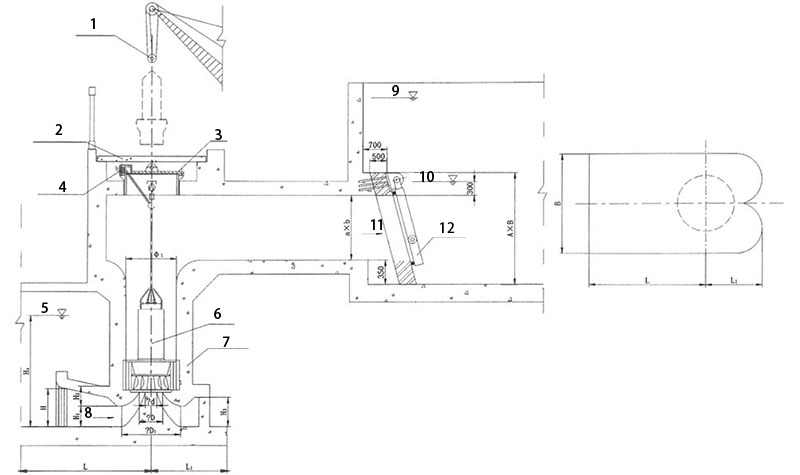
3. Prefabricated concrete shaft installation and dimensions
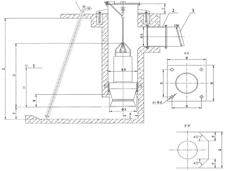
1. Minimum water level
2. Wall penetrating pipe
3. Tap the door
Note:
(1) The dimensions in the table refer to the installation dimensions of the pump and the hydraulic control dimensions designed for the pump station. The hydraulic dimensions designed for the pump station are only for reference.
(2) Size A is determined based on the flow rate to control the flow rate and reduce hydraulic losses. The dimensions in the table are reference values and can be appropriately increased if necessary. Size E is determined based on the specific conditions of the pump station. The above dimensions are determined according to user requirements.
(3) The distance between the pump center and the rear pool wall is less than ≤K.
(4) The center distance between two pumps in the same pool is greater than ≥L.
Size Table for Concrete Prefabricated Shaft Installation (QHB)
| Serial number | Model | ΦA | ΦD | M | N | n-φd | F | H | G | 工 | K | L | Q | P | W | ΦX | Axial water thrust(N) |
| 1 | 350QH0.1-5 | 400 | 600 | 1320 | 1150 | 4-28 | 205 | 555 | 1735 | 210 | 490 | 1450 | 1000 | 240 | 275 | 450 | 1050 |
| 2 | 350QH0.2-11 | 400 | 800 | 1580 | 1350 | 4-36 | 295 | 705 | 2018 | 210 | 590 | 1550 | 1550 | 390 | 275 | 650 | 4950 |
| 3 | 350QH0.3-28 | 400 | 1000 | 1820 | 1600 | 4-40 | 395 | 815 | 2580 | 230 | 690 | 1750 | 1750 | 440 | 510 | 810 | 19550 |
| 4 | 350QH0.3-40 | 400 | 1000 | 1820 | 1600 | 4-40 | 395 | 805 | 3180 | 230 | 690 | 1750 | 1750 | 440 | 500 | 790 | 24650 |
| 5 | 400QH0.3-10 | 400 | 800 | 1580 | 1350 | 4-36 | 295 | 705 | 2018 | 210 | 590 | 1550 | 1550 | 390 | 360 | 650 | 6250 |
| 6 | 500QH0.5-32 | 600 | 1200 | 2120 | 1900 | 4-40 | 395 | 855 | 3210 | 270 | 990 | 2350 | 2350 | 590 | 420 | 810 | 33250 |
| 7 | 500QHB-50 | 600 | 800 | 1580 | 1350 | 4-36 | 395 | 1105 | 2270 | 210 | 590 | 1550 | 1550 | 390 | 600 | 850 | 17550 |
| 8 | 500QH0.6-35 | 600 | 1300 | 2250 | 2000 | 4-40 | 495 | 755 | 2815 | 310 | 990 | 2750 | 2750 | 690 | 390 | 1130 | 45350 |
| 9 | 600QHB-50 | 700 | 1000 | 1820 | 1600 | 4-40 | 445 | 1005 | 2310 | 230 | 690 | 1750 | 1750 | 440 | 600 | 850 | 29550 |
| 10 | 700QH0.9-13 | 800 | 1100 | 1980 | 1700 | 4-40 | 645 | 1205 | 3030 | 230 | 790 | 1950 | 1950 | 490 | 530 | 850 | 19750 |
| 11 | 700QHB-50 | 800 | 1100 | 1980 | 1700 | 4-40 | 645 | 1205 | 2510 | 230 | 790 | 1950 | 1950 | 490 | 530 | 850 | 33450 |
| 12 | 700QH1.1-20 | 800 | 1200 | 2120 | 1900 | 4-40 | 645 | 1005 | 2900 | 270 | 990 | 2350 | 2350 | 590 | 530 | 950 | 35450 |
| 13 | 700QH-40 | 800 | 1100 | 1900 | 1700 | 4-40 | 645 | 1205 | 2530 | 230 | 790 | 1950 | 1950 | 490 | 530 | 850 | 53550 |
| 14 | 900QH-40 | 1000 | 1300 | 2000 | 1800 | 4-40 | 820 | 1200 | 3600 | 300 | 1020 | 3400 | 3400 | 850 | 1020 | 1150 | 48200 |
| 15 | 900QH-50 | 1000 | 1300 | 2000 | 1800 | 4-40 | 820 | 1360 | 3800 | 300 | 1020 | 3400 | 3400 | 850 | 1020 | 1150 | 48200 |
| 16 | 1000QH-40 | 1200 | 1400 | 2250 | 2050 | 4-40 | 840 | 1280 | 3960 | 300 | 1040 | 3480 | 3480 | 870 | 1040 | 1250 | 53600 |
| 17 | 1000QH-50 | 1200 | 1400 | 2250 | 2050 | 4-40 | 840 | 1390 | 4200 | 300 | 1040 | 3480 | 3480 | 870 | 1040 | 1250 | 66200 |
| 18 | 1200QH-40 | 1400 | 1600 | 2400 | 2200 | 4-40 | 910 | 1880 | 4000 | 300 | 1140 | 3800 | 3800 | 950 | 1140 | 1420 | 88000 |
| 19 | 1200QH-40 | 1400 | 1600 | 2400 | 2200 | 4-40 | 910 | 2080 | 4600 | 300 | 1140 | 3800 | 3800 | 950 | 1140 | 1420 | 941600 |
4. Installation and Size of Concrete Prefabricated Shaft with Closed Inlet Channel
① Dustpan shaped inlet channel
1. Cleaning machine
2. Minimum water level
3. Valve maintenance
4. One time pouring of embedded parts
5. Secondary pouring of embedded parts, pouring after on-site welding
6. Second pouring
7. First pouring
8. Floating box flap door
9. Valve maintenance
Note:
(1) The inlet channel can be equipped with elbow shaped, bell shaped, and dustpan shaped channels. The channel dimensions in the installation dimension table are dustpan shaped channels (for reference only).
(2) In addition to meeting the requirements in the table, the submergence depth must also be at least 500mm higher than the upper edge of the inlet of the channel.
(3) Generally speaking, the installation dimensions of the pump section are provided by the supplier, and the submergence depth is jointly determined by the supplier and the design party, and then verified through device testing. The geometric dimensions of the inlet and outlet water channels are calculated by the design unit according to the specifications through numerical modeling, and after preliminary determination, device model testing is carried out. The geometric dimensions of the flow channel provided by the manufacturer are used as a reference for the design unit during design.
(4) The geometric dimensions of the flow channel proposed by the supplier are for reference only by the user and the designer.
Size Table for Installation of Concrete Prefabricated Shaft with Closed Inlet Channel
| Model | H1 | H2 | ΦA | h | ①B | M | N | n-φd | G×H | Pump weight (kg) | Axial water thrust(N) |
| 1200QZB-70 | 1580 | 2150 | 1600 | 950 | 1900 | 2000 | 1750 | 4-40 | 1400×1400 | 7400 | 77700 |
| 1200QZB-100 | 800 | 5890 | 62980 | ||||||||
| 1200QZB-125 | 2250 | 5890 | 54690 | ||||||||
| 1200QZB-160 | 1750 | 5890 | 38390 | ||||||||
| 1300QZB-70 | 1910 | 800 | 1800 | 1150 | 2100 | 2250 | 1950 | 4-40 | 1400×1600 | 9010 | 95300 |
| 1300QZB-100 | 800 | 8010 | 77050 | ||||||||
| 1300QZB-125 | 800 | 8010 | 66950 | ||||||||
| 1300QZB-160 | 800 | 8010 | 46990 | ||||||||
| 1400QZB-70 | 1990 | 1080 | 1900 | 1200 | 2200 | 2350 | 2050 | 4-40 | 1400×1800 | 10010 | 112950 |
| 1400QZB-100 | 800 | 9010 | 91450 | ||||||||
| 1400QZB-125 | 1180 | 9010 | 79350 | ||||||||
| 1400QZB-160 | 800 | 9010 | 55650 | ||||||||
| 1600QZB-100 | 2460 | 800 | 2300 | 1480 | 2600 | 2750 | 2450 | 4-40 | 1400×1800 | 12010 | 134450 |
| 1600QZB-125 | 900 | 12010 | 116750 | ||||||||
| 1600QZB-160 | 800 | 12010 | 81880 | ||||||||
| 1000HB-40 | 1350 | 2050 | 1400 | 750 | 1700 | 1800 | 1550 | 4-40 | 1200×1200 | 6780 | 68990 |
| 1000HB-50 | 2050 | 6280 | 62990 | ||||||||
| 1200HB-40 | 1580 | 2250 | 1600 | 950 | 1900 | 2000 | 1750 | 4-40 | 1400×1400 | 7920 | 79880 |
| 1200HB-50 | 2250 | 7320 | 73880 |
②Bell shaped inflow to size chart
1. Truck crane
2. Concrete activity cover plate
3. Manhole cover
4. Diving wire lead out
5. Minimum water level
6. Submersible pump
7. Concrete shaft
8. Inlet water
9. Maximum water level
10. Minimum water level
11. Water outlet
12. Floating box flap door
| Serial number | Model | φ1 | φD | φD | φd | H₃ | H | H | H: | H | B | L | L | a×b | A×B | Pump weight (kg) |
| 1 | 1200QZB 70 | 1600 | 950 | 1350 | 466 | 300 | 1350 | 438 | 580 | 760 | 2700 | 3400 | 1260 | 1400×1400 | 2400×2400 | 7400 |
| 2 | 1200QZB-100 | 388 | 5890 | |||||||||||||
| 3 | 1200QZB-125 | 306 | 5890 | |||||||||||||
| 4 | 1200QZB-160 | 290 | 5890 | |||||||||||||
| 5 | 1300QZB-70 | 1800 | 1060 | 1520 | 480 | 400 | 1500 | 488 | 650 | 850 | 3000 | 3800 | 1400 | 1400×1600 | 2600×2600 | 9010 |
| 6 | 1300QZB-100 | 432 | 8010 | |||||||||||||
| 了 | 1300QZB-125 | 400 | 8010 | |||||||||||||
| 8 | 1300QZB-160 | 385 | 8010 | |||||||||||||
| 9 | 1400QZB-70 | 1900 | 1170 | 1680 | 576 | 500 | 1650 | 540 | 720 | 940 | 3300 | 4200 | 1560 | 1400×1800 | 2800×2800 | 10010 |
| 10 | 1400QZB-100 | 480 | 9010 | |||||||||||||
| 11 | 1400QZB-125 | 380 | 9010 | |||||||||||||
| 12 | 1400QZB-160 | 358 | 9010 | |||||||||||||
| 13 | 1600QZB-100 | 2300 | 1515 | 2200 | 616 | 600 | 2100 | 695 | 930 | 1200 | 4300 | 5400 | 2000 | 1800×1800 | 2800×2800 | 12010 |
| 14 | 1600QZB-125 | 487 | 12010 | |||||||||||||
| 15 | 1600QZB-160 | 460 | 12010 | |||||||||||||
| 16 | 1000HB2.6-12 | 1400 | 750 | 1150 | 321 | 200 | 1100 | 350 | 450 | 670 | 2400 | 3000 | 1000 | 1200×1200 | 2200×200 | 6780 |
| 17 | 1000HB2.6-12A | 321 | 6280 | |||||||||||||
| 18 | 1200HB3.1-12 | 1600 | 950 | 1350 | 350 | 300 | 1350 | 438 | 580 | 760 | 2700 | 3400 | 1260 | 1400×1400 | 2400×2400 | 7920 |
| 19 | 1200HB3.1-12A | 350 | 7320 |
Other installation forms and accessories
1. Floor standing installation of wellbore
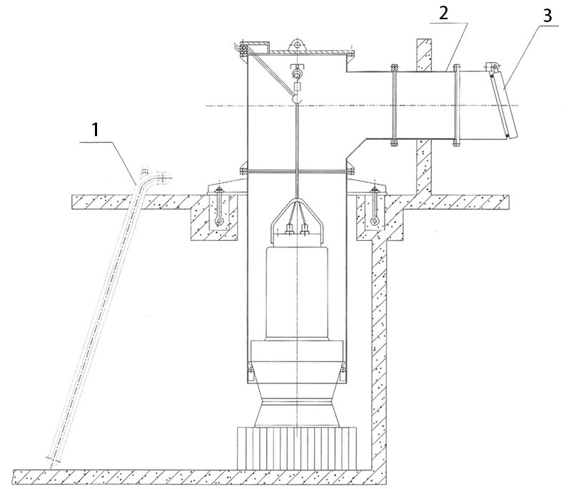
1. Minimum water level
2. Wall penetrating pipe
3. Tap the door
Explanation:
(1) Floor standing installation is an installation method developed on the basis of steel wellbore installation, which has the characteristics of stability and reliability. The pump seat can be fixed by pre embedded anchor bolts.
(2) The elevation of the vertical pipe between the pump seat and the electric pump can be adjusted, and a middle auxiliary support can be provided when the vertical pipe is long.
(3) The position of the water outlet pool can be adjusted by extending the horizontal water outlet pipe.
2. Distributed installation of wellbore
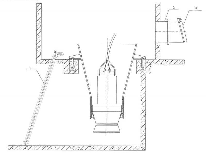
1. Minimum water level
2. Wall penetrating pipe
3. Floating box flap door
Explanation:
This installation method is preferred for the installation of low head submersible electric pumps.
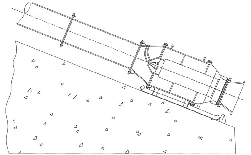
3. Diagonal installation
① Sled installation
Features:
1. Suitable for small and medium-sized units, flexible and convenient, especially suitable for flood control and emergency rescue or situations where temporary pump stations need to be established.
2. Directly using pipelines to transport media, with reliable sealing and no leakage.
3. The civil engineering is simple, the construction amount is small, and the existing ramp construction can be utilized. The construction period is short and the investment is low.
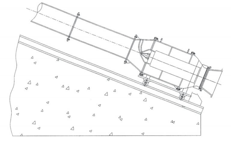
② Pipeline direct installation
Features:
1. It is suitable for Rivers and Lakes where the water level changes frequently.
2. Directly using pipelines to transport media, with reliable sealing, no leakage, and no need to build inlet and outlet water tanks. This method is particularly space saving for the structure of a separate sand room.
3. The civil engineering is simple, the construction amount is small, and the existing ramp construction can be utilized. The construction period is short and the investment is low.
Points to note:
To prevent tipping over, there should be sufficient span in the design.
4. Attachment:
① Floating box flap door
Installation dimension table of floating box flap door
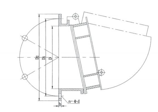
| Diameter of wellbore water outlet | ΦD | ΦD1 | ΦD2 | n-Φd | b |
| 350 | 350 | 445 | 495 | 8-18 | 20 |
| 400 | 400 | 495 | 540 | 8-23 | 20 |
| 500 | 500 | 655 | 710 | 6-27 | 22 |
| 600 | 600 | 705 | 755 | 10-27 | 27 |
| 700 | 700 | 810 | 860 | 12-27 | 27 |
| 800 | 800 | 920 | 980 | 12-27 | 27 |
| 900 | 900 | 1020 | 1075 | 12-27 | 30 |
| 1100 | 1100 | 1220 | 1280 | 12-27 | 30 |
| 1000 | 1000 | 1120 | 1175 | 12-27 | 30 |
| 1200 | 1200 | 1320 | 1380 | 12-27 | 32 |
| 1300 | 1300 | 1430 | 1500 | 12-27 | 32 |
| 1400 | 1400 | 1560 | 1630 | 12-36 | 35 |
| 1600 | 1600 | 1760 | 1830 | 12-36 | 35 |
| 1800 | 1800 | 2000 | 2360 | 12-36 | 40 |
② Rubber slow closing check valve
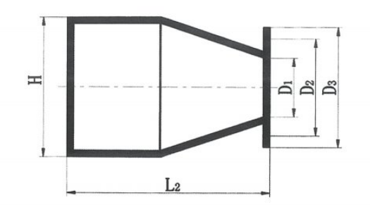
Outline drawing of built-in connection
Outline drawing of sleeve type connection
Outline drawing of flange type connection
Connection size table:
| Nominal diameter (DN) | φ600 | φ800 | φ1000 | φ1200 | φ1400 | φ1500 | φ1600 | φ1800 | φ2000 |
| Valve inner diameter D | φ630 | φ820 | φ1020 | φ1230 | φ1440 | φ1532 | φ1632 | φ1850 | φ2050 |
| Bolt hole center diameter D ₂ | φ795 | φ1000 | φ1240 | φ1450 | φ1680 | φ1760 | φ1880 | φ2220 | φ2400 |
| Outer diameter of flange D | φ840 | φ1050 | φ1290 | φ1510 | φ1740 | φ1830 | φ1950 | φ2320 | φ2500 |
| Bolt hole diameter | 26 | 30 | 30 | 33 | 33 | 36 | 36 | 36 | 36 |
| number of bolts | 20 | 24 | 28 | 32 | 36 | 36 | 40 | 48 | 48 |
| thread specification | M24 | M27 | M27 | M30 | M30 | M33 | M33 | M33 | M33 |
| Rubber valve body length L ₂ | 920 | 1180 | 1432 | 1658 | 1858 | 1925 | 2122 | 2348 | 2600 |
| The total length of the built-in valve tube is L | 1520 | 1888 | 2580 | 2860 | 3280 | 3450 | 3780 | 4150 | 4680 |
| Sleeve type valve pipe straight pipe length Ls | 200 | 200 | 250 | 250 | 300 | 300 | 300 | 400 | 400 |
| Rubber valve body height H | 1050 | 1390 | 1690 | 2030 | 2400 | 2590 | 2760 | 3030 | 3400 |
| Self weight (kg) | 142 | 292 | 452 | 832 | 1025 | 1125 | 1245 | 1425 | 1615 |
Scope of complete supply and ordering instructions
1. Scope of complete supply
| Scope of supply | Installation method | Remarks | ||||
| Shaft type | Prefabricated concrete for closed inlet channel | |||||
| Bend type | Steel standard | Prefabricated concrete | ||||
| Required item | main pump | ★ | ★ | ★ | ★ | The cable length is determined by the user |
| control cabinet | ★ | ★ | ★ | ★ | ||
| Cable fixing device | ★ | ★ | ★ | ★ | The length is determined according to user requirements | |
| Manhole cover device | ★ | ★ | ||||
| Shaft (including tee) | ★ | ★ | ||||
| mounting base | ★ | ★ | ||||
| 1、 Secondary embedded parts | ★ | |||||
| Optional parts | trash rack | ★ | ★ | ★ | ★ | The external dimensions and installation dimensions are determined by the user |
| Wall penetrating pipe | ★ | ★ | ★ | ★ | ||
| terminal box | ★ | ★ | ★ | ★ | ||
| level switch | ★ | ★ | ★ | ★ | ||
| knock on the door | ★ | ★ | ★ | ★ | ||
| Butterfly (gate) valve | ★ | ★ | ★ | ★ | ||
| check valve | ★ | ★ | ★ | ★ | ||
| Flexible rubber hose | ★ | ★ | ★ | ★ | ||
| Vulnerable parts | Inlet sealing ring | ★ | ★ | ★ | ★ | |
| sealing ring | ★ | ★ | ★ | ★ | ||
| Impeller blades | ★ | ★ | ★ | ★ | ||
| bearing | ★ | ★ | ★ | ★ | ||
| mechanical seal | ★ | ★ | ★ | ★ | ||
| O-ring | ★ | ★ | ★ | ★ | ||
2. Ordering Notice
(1) The accurate product model and name, installation form, performance parameters (flow rate, head, motor power), and operating voltage (380V, 660V, 3KV, 6kV, 10KV) should be specified in the contract.
(2) The control cabinet should indicate its starting method (direct starting, autotransformer pressure reducing starting, thyristor soft starting), liquid level control method (floating ball liquid level, pressure transmitter digital liquid level, ultrasonic liquid level), and installation form (indoor or outdoor).
(3) If a terminal box is required, it should be indicated whether it is a control type or a wiring type: indoor or outdoor.
(4) The dimensions that need to be determined by the user in the "scope of supply" should be provided in a timely manner, and the user should also provide equipment installation and construction drawings.
(5) The normal supply length of our company's submersible pump cable is 10m. If the user has special requirements, please specify.
(6) If there are any other special requirements, please contact our technical department before signing the contract.
Scope of complete supply and ordering instructions
1、 Open type inlet (inlet pool)
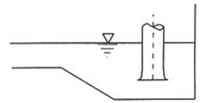
Open type inlet (water tank) has a simple structure and easy construction, and is widely used in small and medium-sized pump stations. The hydraulic design of this type of channel is highly valued both domestically and internationally, and extensive experimental research has been conducted. Many researchers have proposed design criteria for open inlet tanks in the form of empirical coefficients based on experimental results. However, there are significant differences in the criteria proposed by various parties, and there is still no unified or optimal hydraulic design criterion. Below are general design reference criteria.
1. Minimum water level
2. Polygonal rear wall
3. Semi circular rear wall
Comprehensive dimension diagram of inlet pool (different shapes of rear wall)
Geometric dimensions of forward inlet straight inlet pool
| Geometric dimensions of the inlet pool | Japanese Mechanical Society | British Society for Fluid Dynamics Engineering | American Hydraulic Institute | On site testing at Liyang Shuangqiao Station | Suggested value | Terms of Use |
| Pool width Bj/DL |
2.0~2.5 | 2~3 | 2.6~2.8 | 2.0~2.5 | 2.0~2.5 | Take small values for small pumps and large values for large pumps. |
| Suspended high M/DL |
0.5~0.75 | 0.5~0.75 | 0.52~0.59 | 0.5~0.7 | 0.5~0.7 | Take small values for small pumps and large values for large pumps. |
| Rear pool wall T/DL |
0.8~1.0 | 0.75 | 1.2~1.4 | 0.5~0.75 | ||
| Ike Naga XL/DL |
4.0 | 8.0 | 5~8 |
The hydraulic design of an open inlet (inlet pool) is generally based on the inlet diameter D of the horn pipe. The main reason for this is that the water flow into the pump first passes through the cylindrical surface between the horn pipe mouth and the flow channel bottom plate, and then enters the pump through the horn pipe mouth. It is natural to determine the size of the inlet channel based on the diameter of the horn tube as the basic parameter. But the problem is that the current design of the horn tube has not been standardized, and the inlet diameter of the horn tube is a variable. The ratio of the inlet diameter of the horn tube to the diameter of the pump impeller may not be the same. If D. is used as the basic parameter, it will cause confusion in hydraulic design criteria and appear inappropriate. If the horn tube can be standardized, the hydraulic design of the inlet channel should be based on the horn diameter or impeller diameter as the basic parameters. Otherwise, the pump impeller diameter should be used as the basic parameter.
According to the data "Optimization of Hydraulic Design for Pump Station Inlet Channel", the recommended design for open inlet is as follows
(1) Suspended height M
The recommended suspended height is M=(0.68~1.2) D. For larger or smaller horn tube inlet diameters (1.67D.), take the smaller value, and for smaller horn tube inlet diameters (1.46D.), take the larger value: For larger or smaller horn tube inlet diameters, the value of suspended height can still be within this range.
(2) Rear wall distance T
The determination of the distance between the rear walls is basically not affected by the use of a horn tube for water suction. Some water flow must enter the pump from the rear of the horn tube, so a certain distance between the rear walls is necessary; However, the excessively large distance between the rear walls increases the degree of freedom of water flow in the rear wall space, increases the possibility of vortex generation, and requires a corresponding increase in submergence depth. According to the optimization calculation results, the rear wall distance is taken as (0.8-1.0) D. It is sufficient to meet the requirements.
(3) Pool width Bj
In order to allow a portion of the water flow to smoothly enter the pump from both sides and behind the horn pipe, a certain pool width is required: excessively large pool widths can suddenly increase civil engineering investment. The diameter of the horn tube inlet to some extent affects the determination of the optimal pool width. Based on the optimization calculation results, it is recommended that the pool width be (3.5-4.5) D. The inlet diameter of the larger horn tube is taken as the smaller value, and the inlet diameter of the lighter horn tube is taken as the larger value.
(4) Pool length X
In the case of forward inflow, sufficient pool length is necessary to achieve a generally uniform water flow before reaching the horn pipe. The pool length can be determined according to the layout requirements of the upper structure of the pump room, generally taking (7.0~8.0) D. In the case of lateral inflow, the pool water needs to be appropriately increased or necessary rectification measures need to be taken. The determination of pool length is independent of the size of the inlet diameter of the horn tube used.
(5) Flat shape
The calculation results show that the planar shape of the inlet pool has little effect on the working state of the pump: according to experimental data, the planar shape has a certain impact on the hydraulic loss of the inlet pool, with the heart-shaped hydraulic loss being the smallest and the rectangular hydraulic loss being the largest.
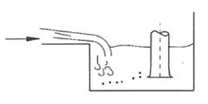
2、 The issues that need to be noted in the design of the inlet pool include:
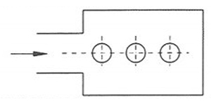
(1) Make the flow in the inlet pool close to natural flow, and the flow should be able to evenly suction each pump.
(2) The configuration of the pump, the position of the inlet, and the design of the shape of the inlet pool should not cause backflow.
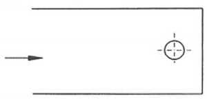
(3) The flow velocity entering the inlet of the water tank should be slow, with a value below 0.7m/s. In addition, it is advisable to maintain a flow velocity of 0.3m/s or less near the pump suction inlet located in the inlet pool.
(4) The flow channel cannot suddenly expand or change direction sharply.
(5) The design size of the inlet pool should not be too large or too small relative to the flow rate of the pump.
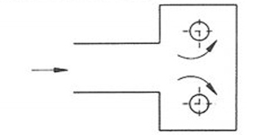
(6) Avoid installing another pump upstream of one pump.
(7) There should be sufficient submergence depth to avoid the generation of air intake vortices.
(8) Lower the bottom of the inlet pipe to smoothly connect it to the inlet pool. At the same time, the ends of the inlet and return pipes in the inlet pool should be submerged in the water, which is beneficial for smooth drainage. In this way, the water flowing in from the inlet pipe will not be sucked into the air and flow into the inlet pool.
(9) To prevent the occurrence of vortices, appropriate anti vortex walls and partition walls should be installed.
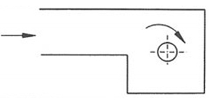
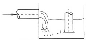
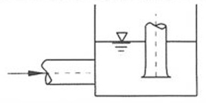
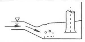
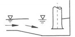
The following table provides examples of incorrect and correct water intake
| Bad example | Precautions | Excellent example |
 |
(2) |  |
 |
(2)、(4) |  |
 |
(5) |  |
 |
(2)、(4) | 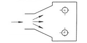 |
 |
(1)、(4)、(6) |  |
 |
(1)、(2) (4)、(6) |
 |
 |
(1)、(2)、(4) | 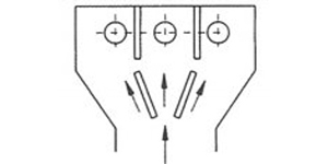 |
 |
(8) |  |
 |
(8) |  |
 |
(8) |  |
3、 Reference diagram for closed inlet channel
1. Elbow shaped inlet channel
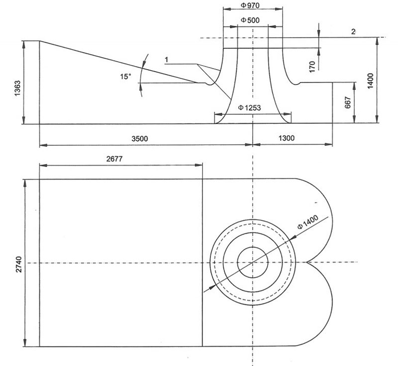
The elbow shaped inlet channel is commonly used and the design and research are relatively mature. The cross-section of the elbow shaped inlet channel gradually shrinks, and the water flow state inside the channel is good with small hydraulic losses; The width of the channel plane is relatively small, usually B/D=2-2.5 (D is the diameter of the pump impeller, B is the width of the channel). In addition to the insufficient elbow shaped inlet channel, the height of the channel is relatively high, which may increase the excavation depth of the pump station foundation pit. Usually Hw/D=1.6~1.8 (Hw is the vertical distance from the center of the impeller to the bottom of the flow channel), and secondly, due to the complex profile, high construction technology requirements are required.
The main contradiction in hydraulic design of elbow shaped inlet channels is the inability to increase the average angle of water flow into the pump, while the uniformity of flow velocity generally meets the requirements. The geometric parameter that has the greatest impact on the average angle of water flow into the pump is the center height Hw of the pump impeller. Its value should not be too small, preferably not less than 1.6 Do. Without significantly increasing civil engineering investment, it is recommended to use a diameter of 1.8D with an impeller diameter of Do=1m, an impeller chamber inlet diameter of D1=0.97D, and a distance of Hp=0.167D from the center of the pump impeller to the inlet of the impeller chamber. As an example design, for different pump impeller diameters and pump impeller chamber diameters, corresponding conversions can be made based on the ratio of pump impeller diameters.
| No. | X, | Y1 | X₂ | Y₂ | B | H | R |
| 1 | 0 | 1940 | 0 | 0 | 2260 | 1940 | 0 |
| 3 | 1210 | 1445 | 1210 | 0 | 2260 | 1445 | 0 |
| 5 | 2420 | 950 | 2420 | 0 | 2127 | 950 | 31 |
| 7 | 2583 | 894 | 2855 | 0 | 1968 | 935 | 75 |
| 9 | 2753 | 873 | 3288 | 37 | 1748 | 992 | 146 |
| 11 | 2908 | 937 | 3682 | 212 | 1456 | 1060 | 258 |
| 13 | 2981 | 1090 | 3919 | 570 | 1192 | 1072 | 379 |
| 15 | 3002 | 1261 | 3992 | 998 | 1041 | 1024 | 459 |
| 17 | 3008 | 1433 | 3992 | 1433 | 984 | 984 | 492 |
| 19 | 3015 | 1633 | 3985 | 1633 | 970 | 970 | 485 |
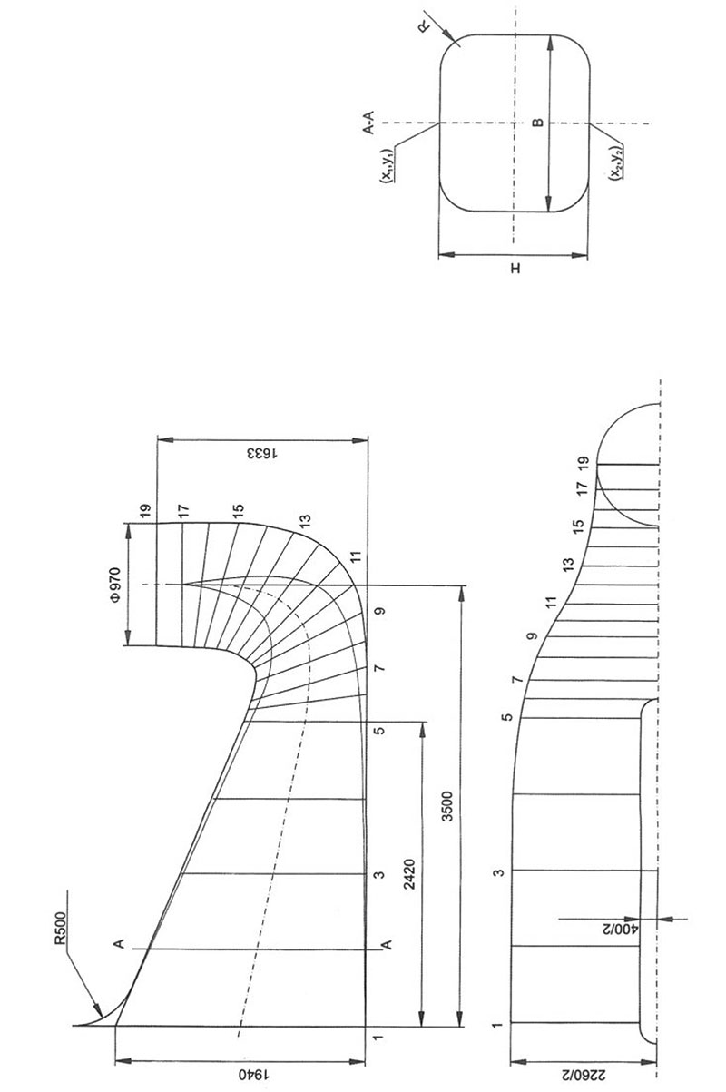
Recommended elbow shaped inlet channel single line diagram (Hw=1.8Do)
2. Bell shaped inlet channel
The significant feature of the bell shaped inlet channel is that the center height of the pump impeller (i.e. the distance from the center of the pump impeller to the bottom plate of the channel) is relatively small, which is of particular importance for pumping stations with poor geological conditions. This type of inlet channel was widely used in some large drainage and irrigation pump stations in Japan in the early days, and has also been applied in the construction of large pump stations in China since the 1970s. Compared with elbow shaped channels, the geometric shape of bell shaped channels is more complex, making their hydraulic design more difficult.
The following figure shows the impeller diameter Do=1m and the inlet diameter of the impeller chamber D1=0.97D. The distance from the center of the water pump impeller to the inlet of the impeller chamber is Ho=0.167Do. Design as an example For different pump impeller diameters and pump impeller chamber sizes, corresponding conversions can be made based on the ratio of pump impeller diameters.
Optimized single line diagram of bell shaped inlet channel (Hw=1.4Do)
1. 1/4 ellipse
2. Impeller centerline
2. Impeller centerline
Related products


Copyright © JINGSHUI PUMP (SHANGHAI) CO., LTD. All Rights Reserved.
Wholesale QH Series Submersible Mixed Flow Pump Manufacturers
China QH Series Submersible Mixed Flow Pump Factory
