English
 Español
 русский
 عربى
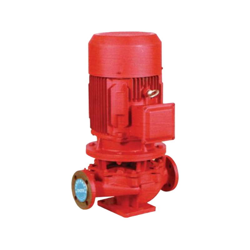
عربىA high pressure fire water pump is a specialized centrifugal or multistage pump designed to deliver water at pressures typically ranging from 7 bar (100 psi) to over 21 bar (300 psi), ensuring sufficient flow and force to suppress fires across large industrial facilities, high-rise buildings, and offshore platforms. Unlike standard water pumps, fire pumps must meet stringent performance standards — such as NFPA 20 or EN 12845 — and are required to maintain rated pressure and flow even under the most demanding emergency conditions.
What Is the Pressure of a Fire Pump?
Fire pump pressure is not a single fixed value — it is determined by the hazard classification of the protected site, the height of the building, and the friction losses in the pipe network. That said, recognized standards and real-world installations consistently produce the following pressure benchmarks:
| Application | Typical Rated Pressure | Typical Flow Rate |
|---|---|---|
| Light hazard commercial building | 7 – 10 bar (100 – 145 psi) | 500 – 1,500 L/min |
| Ordinary hazard industrial facility | 10 – 14 bar (145 – 200 psi) | 1,500 – 4,500 L/min |
| High-rise building (above 50 m) | 14 – 18 bar (200 – 260 psi) | 2,000 – 6,000 L/min |
| Offshore platform / petrochemical | 16 – 21 bar (230 – 300 psi) | 4,000 – 20,000 L/min |
| Foam/deluge system (extra hazard) | 10 – 17 bar (145 – 245 psi) | 5,000 – 30,000 L/min |
Under NFPA 20, a listed fire pump must deliver 150% of its rated flow at no less than 65% of its rated pressure, and must produce at least 140% of rated pressure at zero flow (churn/shutoff condition). These performance curves are verified during factory acceptance testing and annual field tests. A pump that cannot hold rated pressure at churn is considered non-compliant and must be repaired or replaced.
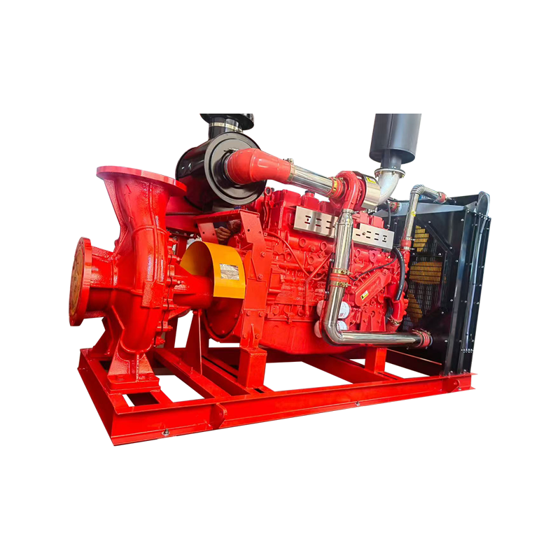
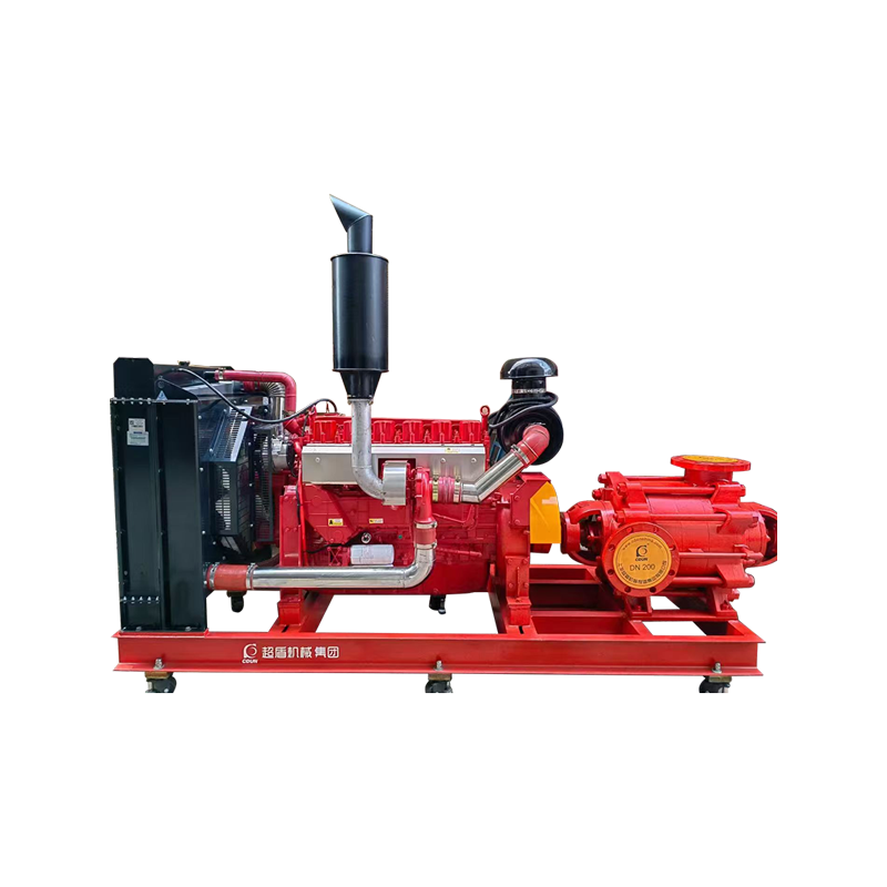
How a High Pressure Fire Water Pump Works
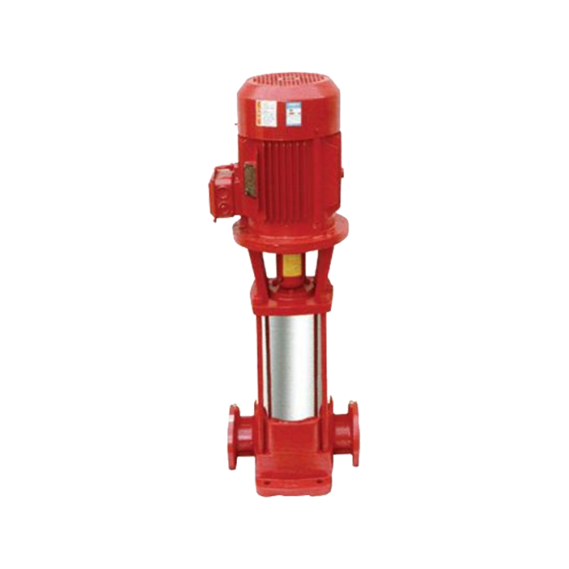
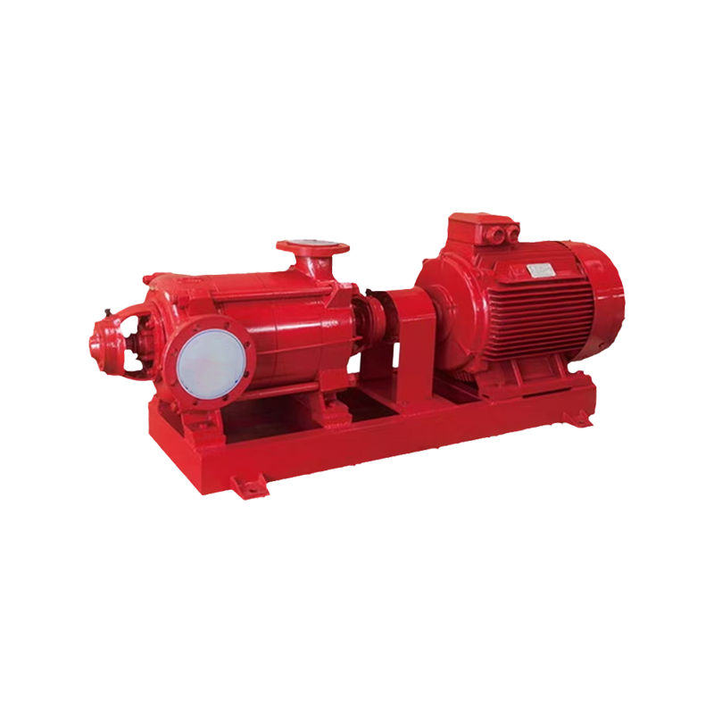
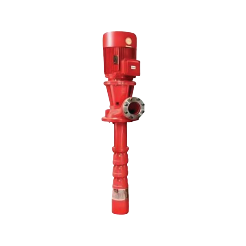
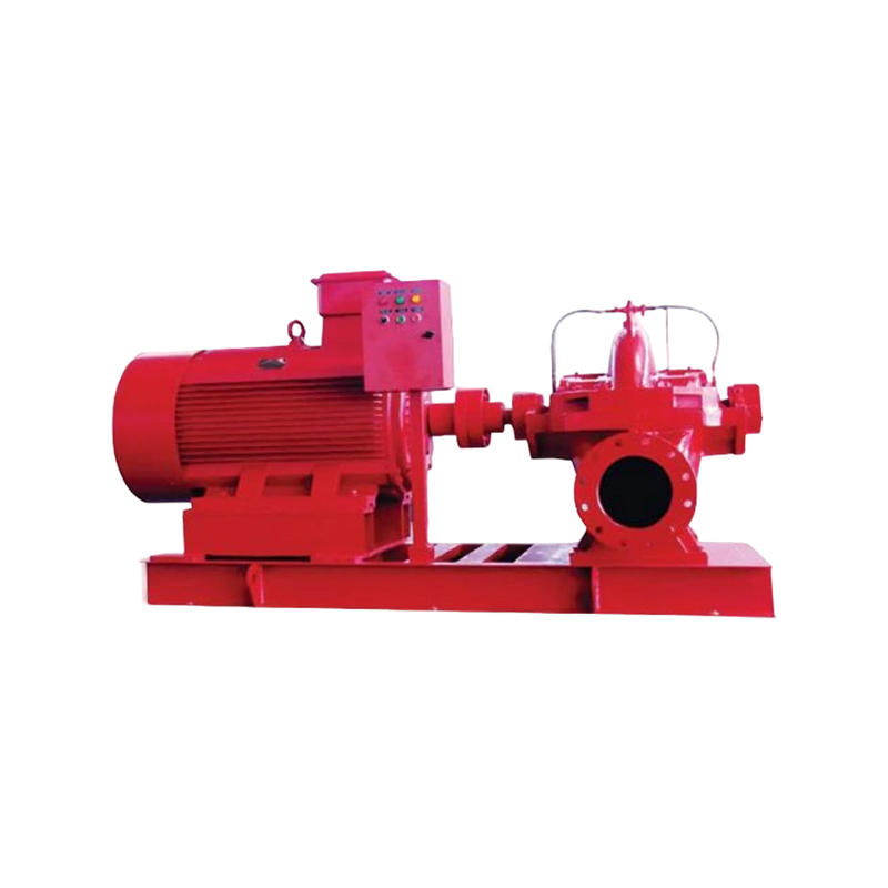
Most **high pressure fire water pumps** are horizontal split-case or vertical turbine centrifugal machines. The impeller rotates at speeds between 1,450 rpm and 3,000 rpm, converting motor or engine shaft energy into pressure energy within the water. In multistage configurations, the water passes sequentially through two or more impeller stages, with pressure compounding at each stage — this is how pumps reach 20 bar and beyond without requiring excessively large single impellers.
Key components and their roles include:
- Impeller: The rotating element that imparts velocity to water. Closed impellers with back vanes are preferred for fire service because they minimize axial thrust and extend seal life.
- Volute or diffuser casing: Converts the water's velocity into pressure. Volute casings are common in single-stage pumps; diffuser bowls are used in vertical turbine and multistage designs.
- Mechanical seal or packing: Prevents water leakage along the shaft. Fire pumps often use robust packing glands that permit a small controlled drip rather than zero-emission seals, improving reliability during infrequent emergency starts.
- Driver — electric motor or diesel engine: NFPA 20 requires a backup diesel driver whenever the electric supply is not from two independent sources. Diesel drivers must start automatically within 10 seconds of a pressure drop signal.
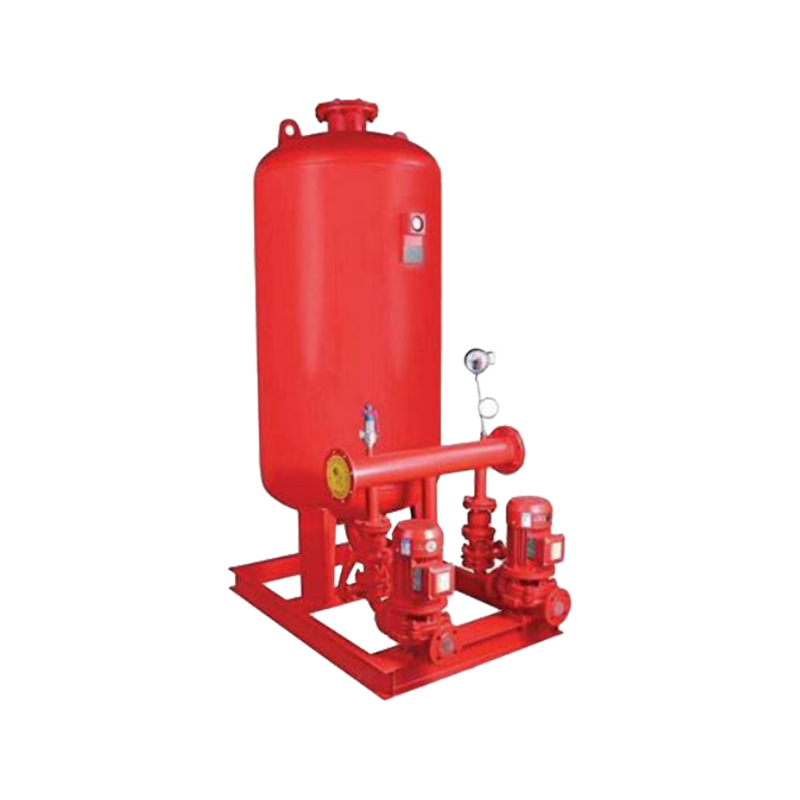
- Controller: Monitors system pressure continuously. When pressure falls below the set start point (typically 0.3 – 0.5 bar below system pressure), the controller starts the pump automatically without human intervention.
- Jockey (pressure maintenance) pump: A small auxiliary pump that compensates for minor leaks, preventing the main fire pump from cycling unnecessarily. If the jockey pump cannot maintain pressure, the main pump starts.
Can a High Pressure Fuel Pump Cause Misfire?
Yes — a faulty high pressure fuel pump is a well-documented cause of engine misfires, and understanding why helps distinguish fuel system faults from ignition or mechanical faults. While this question applies to vehicle and generator engines rather than the fire pump itself, it is directly relevant because many fire pump sets use diesel engines as backup drivers, and engine reliability is critical in emergency scenarios.
A high pressure fuel pump in a common-rail diesel or GDI petrol engine is responsible for pressurizing fuel to 1,000 – 2,500 bar (diesel) or 150 – 350 bar (GDI petrol) before it is injected into the cylinder. When the pump under-delivers, the following misfire mechanisms occur:
| Fuel Pump Fault | Effect on Combustion | Observable Symptom |
|---|---|---|
| Worn pump lobes / plunger | Insufficient rail pressure; lean mixture | Misfire on acceleration, DTC P0087 |
| Sticking pressure control valve | Erratic rail pressure; uneven injection | Rough idle, intermittent misfire |
| Contaminated pump (metal debris) | Injector damage; spray pattern disrupted | Multi-cylinder misfire, smoke |
| Cavitation from low feed pressure | Air bubbles in high-pressure circuit | Hard start, misfire at cold idle |
Diagnosis typically involves recording live fuel rail pressure data with an oscilloscope or scan tool during the misfire event. A healthy common-rail system maintains stable rail pressure within 50 bar of target across all engine speeds. A drop greater than 100 bar under load, or pressure that cannot reach target at idle, points strongly to the high pressure pump rather than the injectors or ECU.
Why Do High Pressure Fuel Pumps Fail?
High pressure fuel pump failures share several root causes that apply both to vehicle engines and to the diesel drivers fitted to fire pump sets. Identifying these causes early prevents the catastrophic scenario of a fire pump engine failing to start during an emergency.
Lubrication Failure from Low-Lubricity Fuel
High pressure fuel pumps in diesel engines rely on the fuel itself for internal lubrication of the pump plungers and lobes. Ultra-low sulphur diesel (ULSD), which has replaced higher-sulphur grades globally, has reduced lubricity. Pumps running on ULSD without a lubricity additive show cam lobe wear rates 30–50% higher than those documented on older fuel grades. Biodiesel blends (B7 or higher) restore lubricity and extend pump life measurably.
Water and Microbial Contamination
Diesel stored in fire pump day tanks for extended periods — sometimes 6 to 18 months without turnover — is highly susceptible to water ingress through condensation and microbial growth. Water in the fuel circuit causes corrosion pitting on pump plungers within weeks. NFPA 110 recommends fuel testing at least annually and complete fuel replacement every 12–18 months for emergency generator and fire pump applications.
Metal Particle Contamination
Debris from corroded tanks, poorly flushed fuel lines, or a failing injector can recirculate through the high pressure circuit. Particles as small as 4 microns can score precision pump components toleranced to 1–2 microns. A 10-micron fuel filter on the low pressure (feed) side provides the first defense; the high pressure pump itself has clearances far tighter than most filter ratings, making upstream cleanliness essential.
Cavitation from Inadequate Feed Pressure
The high pressure pump requires a minimum positive suction head from the low pressure lift or transfer pump. If the feed pump is worn, the filter is blocked, or the fuel tank is nearly empty, cavitation occurs inside the high pressure pump. The resulting vapor bubble collapse erodes internal surfaces within hours of sustained cavitation. Monitoring low-pressure fuel circuit pressure is the most practical preventive measure.
Thermal Fatigue from Infrequent Operation
A fire pump diesel engine that is started only for monthly test runs experiences repeated cold-start thermal cycles with minimal warm running time. High pressure pump seals and elastomers that never reach full operating temperature degrade from oxidation and ozone exposure rather than wear. Weekly no-load runs of at least 30 minutes, as recommended by NFPA 25, significantly extend seal and pump life compared to monthly short-duration tests.
Selecting the Right High Pressure Fire Water Pump
Choosing a fire pump system involves matching the pump curve to the hydraulic demand of the system at every point of operation — not just the design point. The following checklist covers the most critical selection criteria:
- System demand point: Calculate the required flow (L/min or GPM) and residual pressure at the most remote or most demanding sprinkler or hydrant outlet. The pump's rated point must meet or exceed this demand.
- Shutoff (churn) pressure: Verify that the pump's zero-flow pressure does not exceed the pressure rating of the weakest system component, including valves, fittings, and sprinkler heads.
- Net positive suction head available (NPSHa): For suction lift installations, NPSHa must exceed the pump's NPSHr by at least 0.5 – 1.0 m at all operating conditions to prevent cavitation.
- Driver sizing: The motor or engine must be sized for the maximum power demand on the pump curve, which for centrifugal pumps typically occurs at maximum flow (run-out), not at the rated point.
- Listing and certification: Confirm UL listing, FM approval, or equivalent (CE/EN 12845) as required by the local authority having jurisdiction (AHJ). Unlisted pumps are not accepted for life-safety systems in most jurisdictions.
- Redundancy: NFPA 20 requires an automatic backup driver (diesel) unless two independent electric power sources are available. Many high-risk sites install two complete pump sets for N+1 redundancy.
- Corrosion resistance: For seawater or brackish water supply, specify bronze-fitted or all-stainless wetted components. Standard cast-iron impellers and casings corrode rapidly in chloride environments.
Maintenance Practices That Prevent Pump and Engine Failures
A fire pump that fails to start during an emergency is worse than no pump at all, because the protected facility will have been designed around its presence. The following maintenance intervals are drawn from NFPA 25 (inspection, testing, and maintenance of water-based fire protection systems) and represent minimum requirements:
| Task | Frequency | Pass Criterion |
|---|---|---|
| Visual inspection of pump room | Weekly | No leaks, alarms clear, fuel level above 2/3 tank |
| No-load automatic start test | Weekly | Pump starts within 10 s (diesel) or 30 s (electric) |
| Flow test at 100% rated capacity | Annually | Rated pressure at rated flow; within 5% of baseline |
| Diesel engine oil and filter change | Annually or per manufacturer | Oil analysis within acceptable limits |
| Fuel quality test and polishing | Annually | Water content below 200 ppm; microbial count negative |
| Pump packing / seal inspection | Annually | Controlled drip (packing) or zero leakage (mechanical seal) |
| Coupling alignment check | Every 3 years or after any work | Angular and parallel misalignment within OEM tolerance |