 English
 Español
 русский
 عربى
عربىHigh Pressure Fire Water Pump Guide: Sizing, Types & Testing
700–2,000 kPa typical pressure
500–8,000 L/min flow range
NFPA 20 primary standard
150% rated flow test capacity
A high pressure fire water pump is a centrifugal or positive displacement pump engineered specifically to deliver water at elevated pressure and high flow rate to a fire suppression system — sprinkler networks, hydrant risers, deluge systems, or foam systems — within a building or industrial facility. Unlike standard water supply pumps, fire pumps are designed, tested, and certified to a demanding performance standard: they must operate reliably at the exact pressure and flow the system requires, on demand, after potentially months or years of standby, with no tolerance for failure at the moment of a fire event.
On the related questions: high pressure pumps of any type — fuel or water — can develop noise when bearings, seals, or impellers wear, and this noise is a reliable early warning of impending failure. High pressure fuel pumps do fail, typically due to fuel contamination or inadequate lubrication. High flow water pumps absolutely work and are the industry standard for industrial and municipal fire protection — their performance is a function of correct sizing, installation, and maintenance rather than any inherent limitation of the technology.
What a High Pressure Fire Water Pump Does
The primary function of a fire pump is to boost water pressure from the available supply — whether a municipal main, a storage tank, or a natural water source — to the pressure required by the fire suppression system at its most remote or highest point. When municipal supply pressure is adequate at full system flow, a fire pump is not needed. In most mid-rise and high-rise buildings, industrial facilities, and large warehouses, the required pressure exceeds what a municipal main can supply at the necessary flow rate, making a dedicated fire pump essential.
The performance requirement is defined by two simultaneous values that must be met together, not independently:
Pressure (Head)
The residual pressure at the system's most remote sprinkler or hydrant outlet at full design flow. Typically expressed in bar, kPa, or psi. A typical commercial high-rise fire suppression system requires 7–10 bar (700–1,000 kPa) at the most remote outlet. An industrial deluge system may require 12–17 bar. The pump must maintain this pressure at all flow rates from minimum to maximum design flow.
Flow Rate
The total volume of water the system demands when operating — the sum of all active sprinkler heads or outlets. A 20-head sprinkler zone at 80 L/min per head requires 1,600 L/min total flow. An industrial foam deluge system protecting a large tank farm may require 5,000–15,000 L/min. The pump must deliver this flow without pressure dropping below the minimum requirement at the most remote point.
NFPA 20 (the primary North American standard for the installation of stationary pumps for fire protection) requires that a fire pump demonstrate at least 150% of rated flow at 65% of rated pressure during acceptance testing. This ensures the pump has adequate hydraulic capacity above its design point to handle any realistic demand scenario.
Types of High Pressure Fire Water Pump — Which One for Which Application
Fire pump types are classified by driver (electric motor, diesel engine, steam turbine), pump configuration (horizontal split-case, vertical turbine, end-suction, in-line), and primary application. Each combination suits a different set of building type, water supply, and regulatory constraints.
| Pump Type | Driver | Typical Pressure | Flow Range | Best Application |
|---|---|---|---|---|
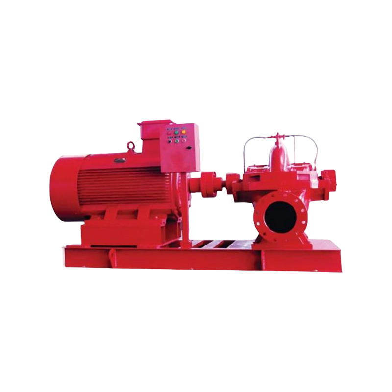
| Horizontal split-case | Electric / diesel | 7–17 bar | 500–10,000 L/min | Commercial buildings, industrial plants |
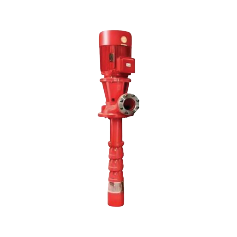
| Vertical turbine | Electric / diesel | 10–30 bar | 1,000–15,000 L/min | Deep water tanks, wet pits, high-rise |
| End-suction | Electric | 5–12 bar | 200–2,000 L/min | Small commercial, light industrial |
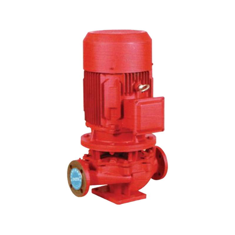
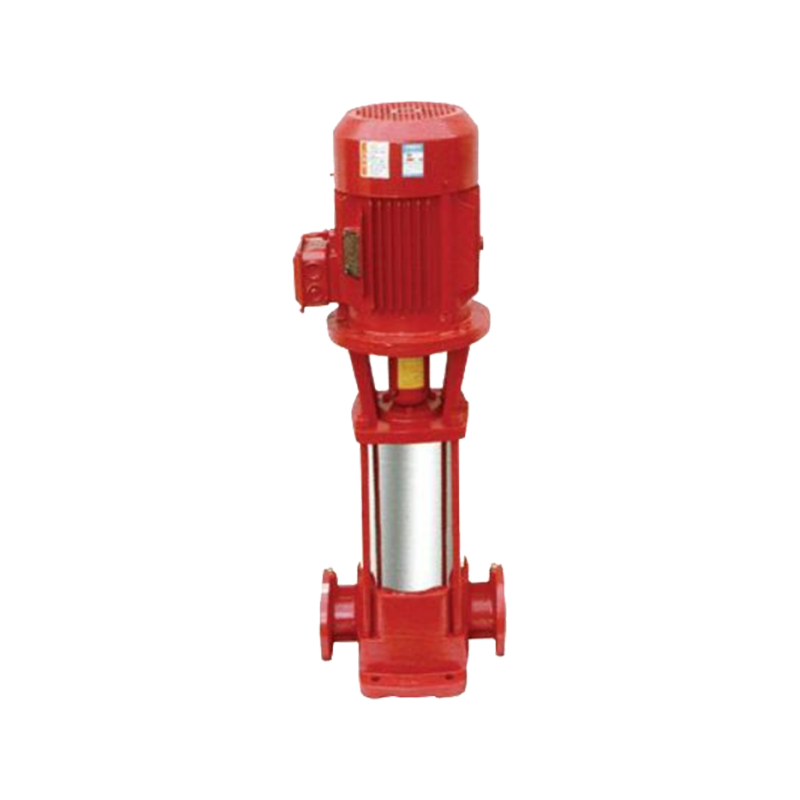
| In-line (vertical) | Electric | 5–10 bar | 200–1,500 L/min | Space-constrained pump rooms |
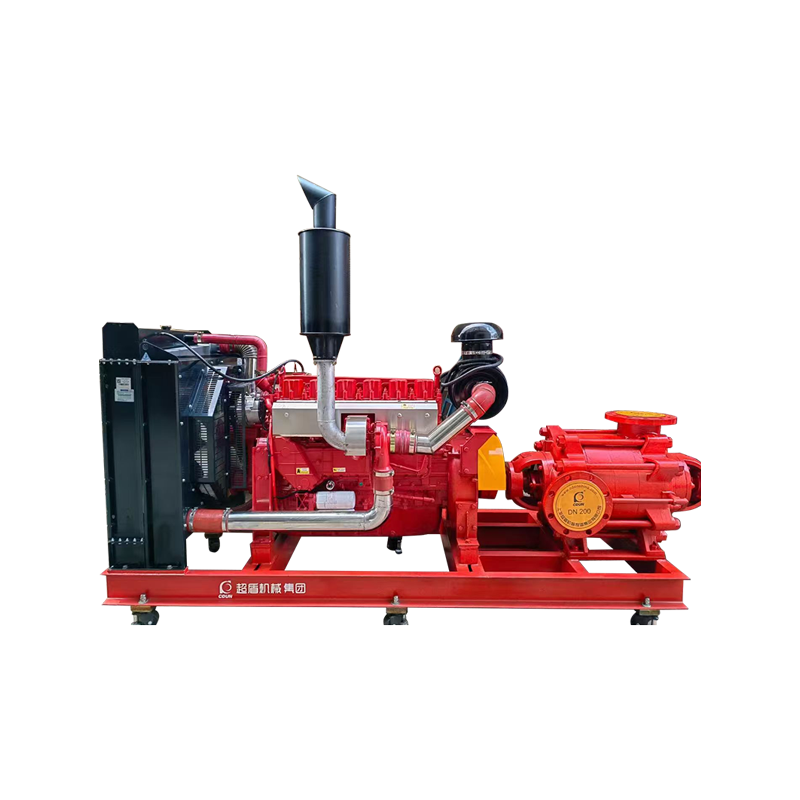
| Multistage high-pressure | Electric / diesel | 20–60 bar | 100–2,000 L/min | High-rise above 50 floors, mist systems |
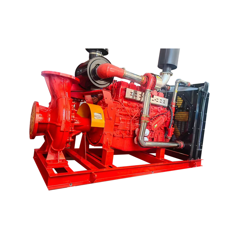
| Skid-mounted diesel | Diesel (self-contained) | 7–17 bar | 500–6,000 L/min | Remote sites, no reliable power supply |
Fire pump types classified by configuration, driver, pressure output, flow rate, and primary application
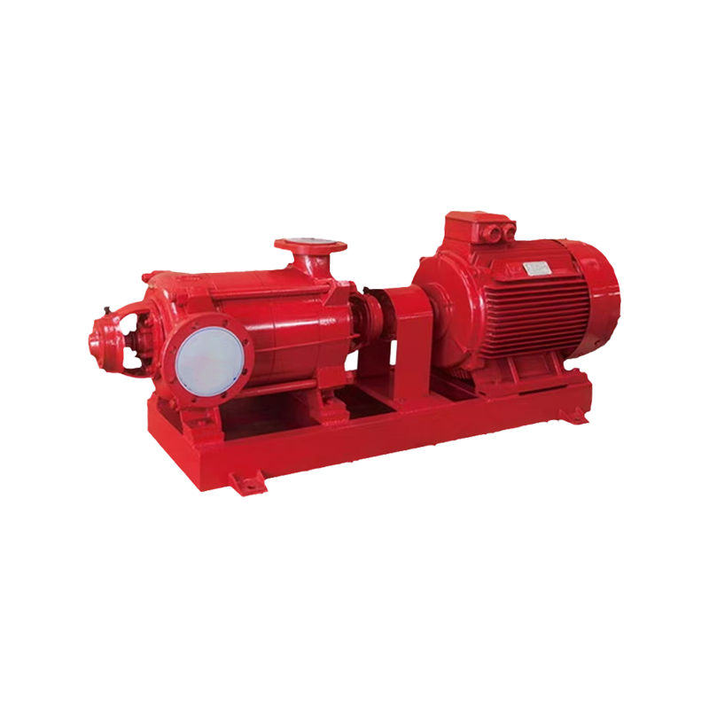
The horizontal split-case pump is the most widely installed type in commercial and industrial fire protection because its bearing arrangement — with the shaft supported on both sides of the impeller — produces high radial load capacity and long bearing life under the variable flow conditions experienced in fire pump service. Horizontal split-case pumps are also easily inspectable and maintainable without disturbing the pipe connections, as the casing splits along a horizontal plane allowing full impeller access.
Does a High Pressure Pump Make Noise — Warning Signs and What They Mean
High pressure pumps of any type — fire water, fuel, hydraulic, or process — develop characteristic noises when components begin to wear or fail. These sounds are diagnostically specific: different failure modes produce different audible signatures, and identifying the noise correctly determines the repair action.
- Cavitation — a grinding or gravel-like rattling sound: The most common and most damaging noise in a centrifugal fire pump. Cavitation occurs when the inlet pressure is insufficient to prevent water at the impeller eye from vaporising into bubbles, which then collapse violently against the impeller vanes as pressure increases through the pump. The collapse of thousands of vapour bubbles per second against the impeller produces a characteristic rattling or gravel sound and causes progressive pitting erosion of the impeller surface. A fire pump cavitating during a weekly test run indicates insufficient suction head — check for suction pipe restrictions, partially closed suction valve, or undersized suction pipe. Sustained cavitation can destroy a pump impeller within 50–200 operating hours.
- Bearing noise — a high-frequency whine or rumble: Worn or inadequately lubricated radial or thrust bearings produce a characteristic high-pitched whine (early wear) or low rumble (advanced wear with spalling). Fire pumps in standby service that are tested for only 30 minutes per week per NFPA 25 requirements have bearings that are essentially in static storage for the remaining 167.5 hours of the week. Static storage causes lubricant migration away from the bearing surfaces — a problem that worsens with time and produces early bearing noise before any measurable deterioration in pump hydraulic performance. Re-grease bearing housings on the manufacturer's schedule regardless of low operating hours.
- Mechanical seal leak — a wet hissing or drip: A failing mechanical seal allows a pressurised water mist to escape at the shaft, often accompanied by a faint hissing or an audible drip into the collection pan. A small amount of controlled weeping (a few drops per minute) is normal in packed gland designs; a continuous stream or spray is not. Seal failure in a fire pump does not immediately cause pump failure but degrades reliability and should be repaired at the next scheduled maintenance window.
- Impeller imbalance — cyclic vibration and low-frequency hum: A partially blocked or eroded impeller loses dynamic balance, causing shaft vibration at rotational frequency (typically 25–50 Hz) and its harmonics. This manifests as a hum felt in the pump casing and heard as a regular low-frequency beat. Vibration analysis using an accelerometer on the bearing housing confirms the source. Blocked impeller passages also reduce pump flow capacity — the pump delivers less than rated flow at rated pressure, which in a fire event means the protected area may not receive adequate suppression.
Do High Pressure Pumps Go Bad — Failure Modes and Causes
High pressure pumps do fail, across all types — fire water, fuel, hydraulic — and the failure mechanisms are well understood. In fire water pumps, the failure modes are particularly critical because the pump must operate correctly on demand at a moment's notice, often after extended standby periods. The most common causes of fire pump failure in service:
- Inadequate maintenance and testing: NFPA 25 (the standard for inspection, testing, and maintenance of water-based fire protection systems) requires weekly churn tests, monthly flow tests to system demand, and annual full-flow tests. Surveys of fire pump failures during actual fire events consistently show that over 60% of pumps that failed to operate correctly had not been tested or maintained to the required schedule. The pump appeared operational during casual inspection but failed because bearing degradation, seal failure, or driver issues had not been detected without test operation.
- Water quality and corrosion: A fire pump may sit with static water in its casing for months between test operations. Stagnant water promotes microbiological growth (microbiologically influenced corrosion, MIC) that pits cast iron casings and stainless impellers from the inside. Water with high mineral content leaves scale deposits in impeller passages, reducing hydraulic efficiency and increasing vibration. Annual flushing and internal inspection are the countermeasures — not optional in facilities with water quality concerns.
- Suction supply failure: A fire pump cannot create water — it can only boost pressure from an available supply. If the supply tank is empty, the suction valve is closed, or the suction pipe is blocked, the pump runs dry and destroys itself within minutes. Dry-running detection (via flow switch or pressure switch on the suction side) should trip an alarm, not shut the pump down — in a fire, a pump running dry is preferable to no pump at all, but the condition must be alarmed and investigated immediately.
- Driver failure: An electric motor-driven fire pump requires a reliable power supply that is maintained even when the main facility power fails — NFPA 20 requires a dedicated power feed from the service entrance that bypasses the main distribution board, or an on-site backup generator. A diesel-driven fire pump is the alternative for sites with unreliable power, but diesel engines that sit idle for months develop fuel degradation, injector fouling, and battery discharge issues. Diesel fire pump starting failures are among the most common causes of fire pump system unavailability in remote industrial locations.
Do High Flow Water Pumps Work for Fire Protection?
Yes — high flow water pumps are not only effective for fire protection, they are the engineering standard for all large-scale fire suppression. The concern behind the question is usually whether a high-flow pump will maintain adequate pressure at extreme flow conditions, or whether the pump will fail to start or sustain operation under fire demand. Both concerns are addressed by the NFPA 20 design and testing framework.
A properly sized fire pump maintains pressure within its defined envelope across the full range of operating flow from shutoff (no flow) to 150% of rated capacity. The typical performance curve for a listed fire centrifugal pump shows:
| Operating Point | Flow (% of Rated) | Pressure (% of Rated) | NFPA 20 Requirement |
|---|---|---|---|
| Shutoff (churn) | 0% | Max 140% of rated | Must not exceed 140% rated pressure |
| Rated point | 100% | 100% | Design point — certified performance |
| Overload test | 150% | Min 65% of rated | Must maintain minimum 65% rated pressure at 150% flow |
NFPA 20 required performance envelope for listed fire centrifugal pumps
The 150% flow / 65% pressure requirement ensures that even in a scenario where demand exceeds the design case — multiple zones operating simultaneously, additional hose streams opened by the fire brigade — the pump continues delivering usable pressure rather than collapsing to zero head. This performance guarantee is verified by a physical test at the pump manufacturer and repeated at acceptance testing on site before the system is placed in service.
Selecting and Sizing a High Pressure Fire Water Pump
Correct pump selection begins with a hydraulic calculation of the fire suppression system — not with a catalogue choice. The system hydraulic design determines the demand point (required flow and pressure at the pump discharge) that the pump must meet. Selecting a pump without a prior hydraulic calculation is the most common cause of undersized or oversized fire pump installations.
- System demand calculation: Calculate the most hydraulically remote design area of the sprinkler system (or the worst-case combination of hydrants and sprinklers operating simultaneously). The hydraulic calculation outputs a flow in L/min and a residual pressure in bar at the base of the riser. Add the friction losses through all pipe, fittings, check valves, and the pump discharge manifold to arrive at the required pump discharge pressure. This is the design demand point on the pump performance curve.
- Pump curve selection: The pump's performance curve must pass through or above the design demand point — meaning the pump delivers at least the required pressure at the required flow. The demand point should fall between 80% and 100% of the pump's rated flow on its performance curve. A pump selected so that the demand point is at only 30–40% of rated flow will run in the right-side "runout" condition during peak demand and will not maintain pressure — this is a sizing error, not a pump failure.
- Net positive suction head (NPSH): The available NPSH at the pump suction must exceed the pump's required NPSH by a safety margin of at least 0.6 m (2 ft). Available NPSH is a function of suction supply pressure (or tank elevation), friction losses in the suction pipe, and water temperature. Failure to verify NPSH results in cavitation at full demand — exactly the condition where the pump must perform correctly.
- Driver sizing: The electric motor or diesel engine must be sized to meet the pump's maximum power demand — which in a centrifugal pump occurs at maximum flow (150% rated condition), not at the rated point. Motor power should be sized at 115–125% of the shaft power at 150% rated flow to prevent motor overload tripping during high-demand conditions. A tripped motor during a fire event is a pump failure regardless of the pump's own mechanical condition.
Maintenance Schedule for High Pressure Fire Water Pumps
A high pressure fire water pump that is correctly specified and installed will remain reliable for its design life — typically 25–40 years for a centrifugal pump with a cast iron casing and bronze impeller — only if it receives the maintenance prescribed by NFPA 25 and the pump manufacturer. The following schedule is the minimum for compliance and reliable operation:
- Weekly — churn test (no-flow test): Start the pump automatically (via pressure drop simulation) and run for a minimum of 10 minutes. Record suction pressure, discharge pressure, and packing/seal condition. This verifies driver start, controller function, and basic pump operation without requiring discharge to drain. Diesel-driven pumps must run for 30 minutes minimum to ensure the engine reaches operating temperature and exercises the cooling system.
- Monthly — flow test at system demand: Open the test header to flow water through the system at the rated pump demand point. Record suction pressure, discharge pressure, and flow rate. Compare against the pump's certified performance curve. A degradation of more than 5% from the certified performance at the test point indicates impeller wear, internal recirculation wear, or pipe restriction and requires investigation before the annual test.
- Annually — full performance test at 100% and 150% rated flow: Conduct a full three-point performance test (shutoff, rated, and 150% rated flow) per NFPA 25 Section 8.3. Record all parameters against the original acceptance test data. Any point that deviates by more than 5% from original performance triggers a hydraulic inspection of the pump. Lubricate all bearings, inspect and replace mechanical seals or packing if required, verify coupling alignment, and test all controller functions including automatic start, manual start, and alarm outputs.
- Every 5 years — internal inspection and impeller measurement: Disassemble the pump and measure impeller diameter, wear ring clearances (allowable wear is typically double the new clearance), and shaft straightness. Excessive wear ring clearance reduces volumetric efficiency — the pump circulates water internally rather than delivering it to the system, reducing effective flow without a corresponding pressure drop that would be detected in routine testing. Wear rings are inexpensive to replace; a worn impeller reduces pump performance permanently until replaced.
Related products
Copyright © JINGSHUI PUMP (SHANGHAI) CO., LTD. All Rights Reserved.
Custom Water Supply/Drainage, Water Treatment, Fire Pump Systems Manufacturers
